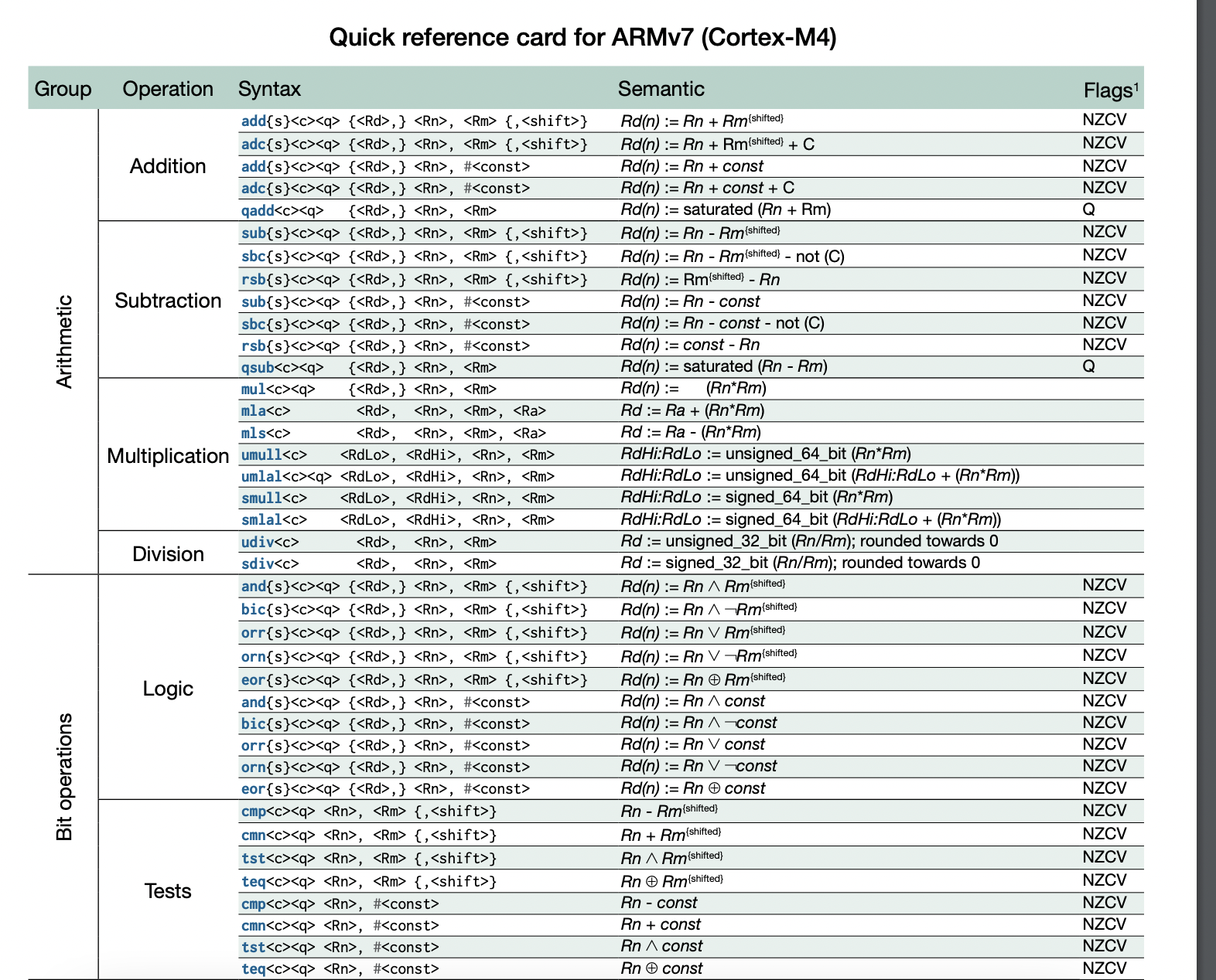
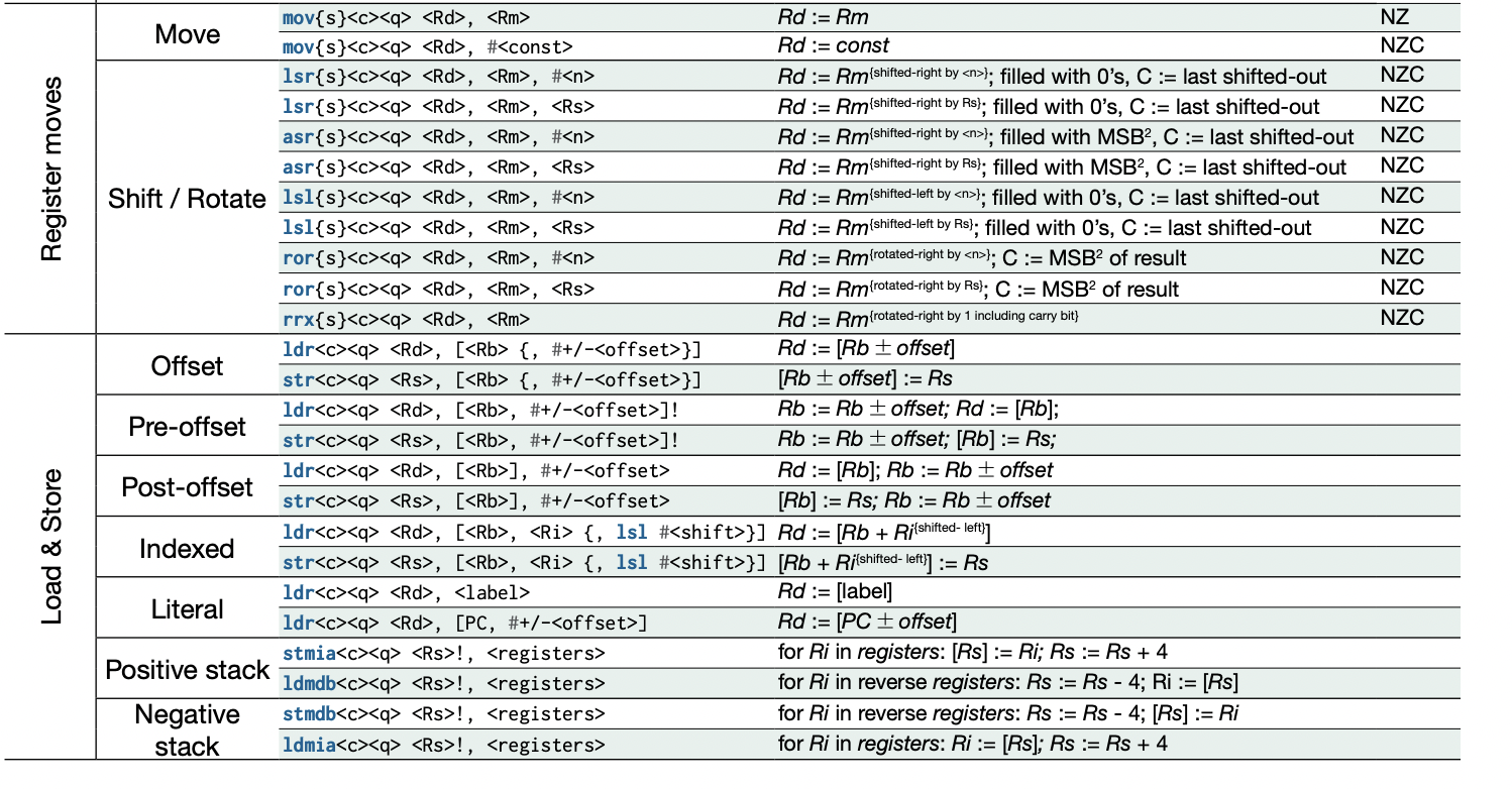
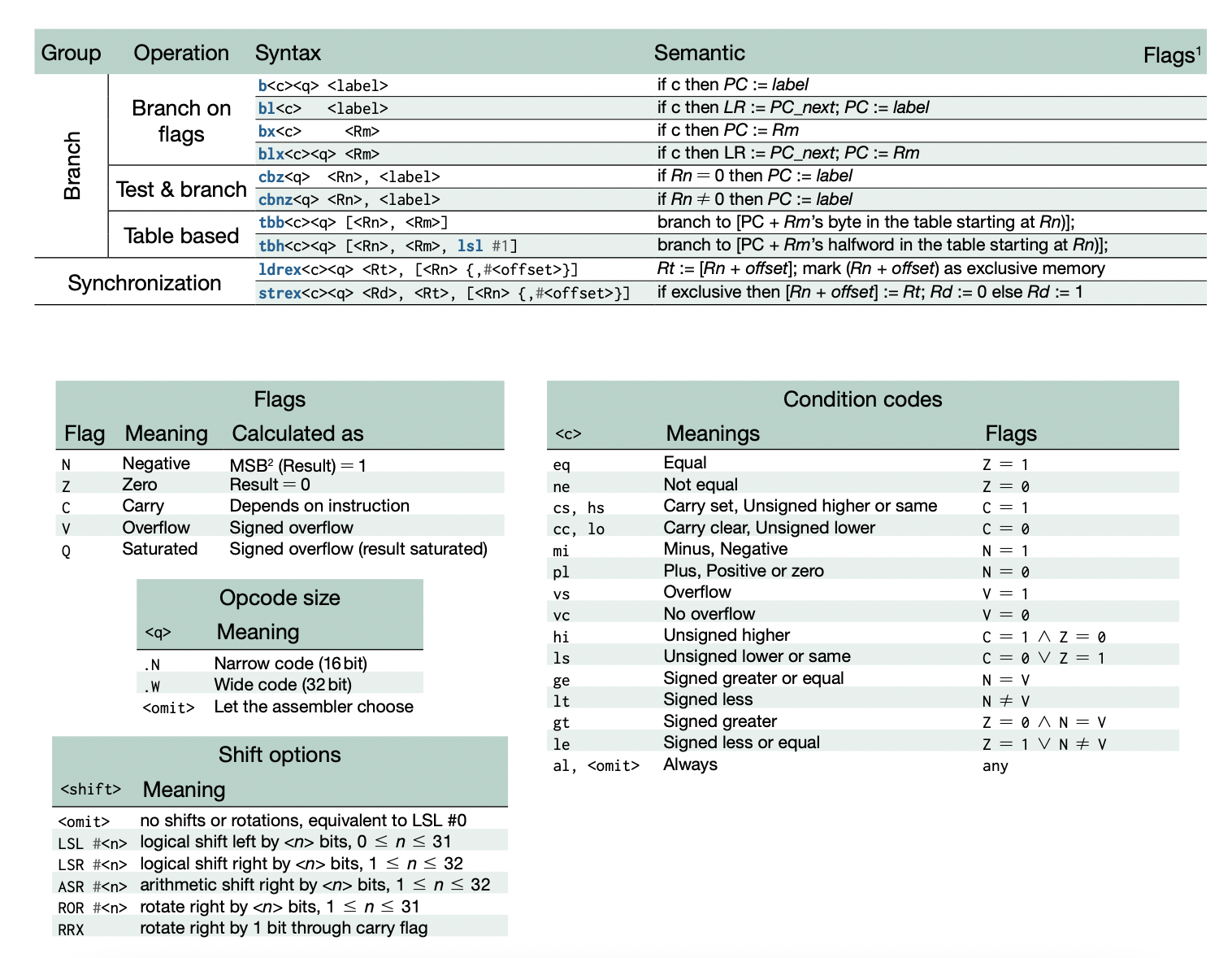
CSS 422 - Hardware and Computer Organization
CPU Arcitechture and Operation
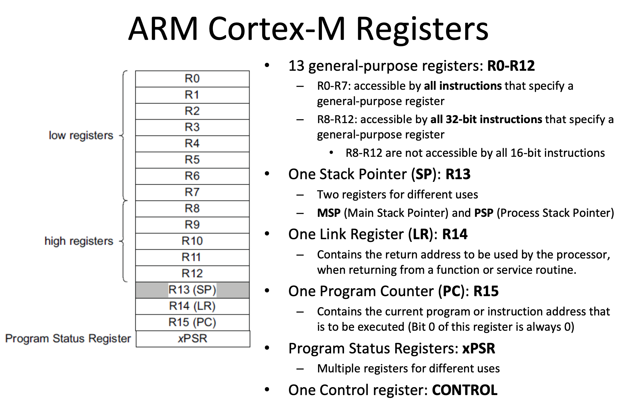
Registers
There are three types of registers
Data Registers
These hold values that we're storying
Flag Registers
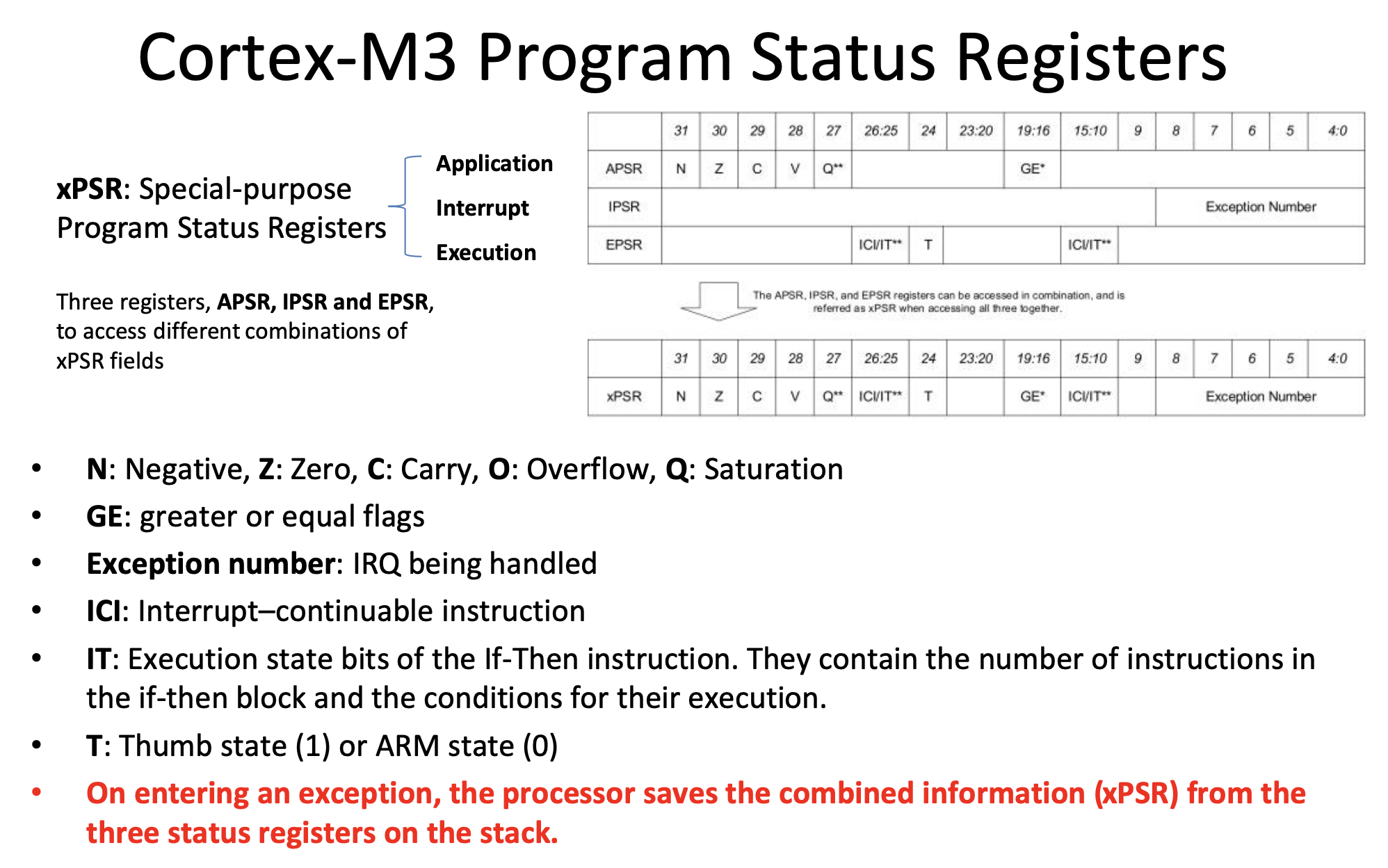
Flag registers are treated as individual bits. They bring together settings/conditions of the processor. It shows the status and condition of the processor.
Each bit in a flag status register indicate a specific thing.
- Z flag (Z) is set to 1 if the result of some operation is equal to 0. If the result is anything other than 0, it's set to 0.
- Sign flag (N) - set to 1 if result is less than zero (negative) (N flag)
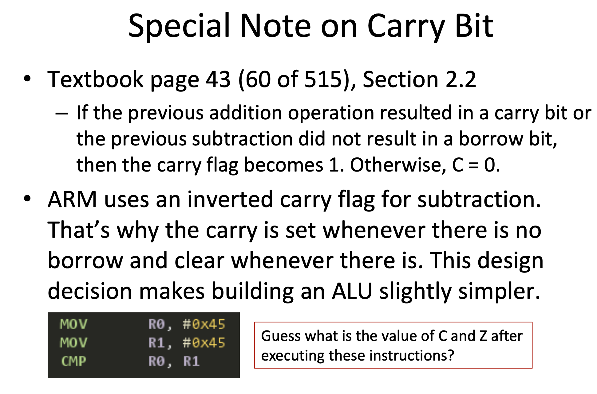
- Carry flag (C) - if a carry pops out of the most significant column, it's "placed" in the carry flag, or otherwise, it's sets the value to whatever the carryout is.
- Overflow Flag (V)- set to 1 if there is a 2's compliment over flow (negative plus negative = 0, or positive plus positive = 1)
Example
01011001 + 00110111 = 10010000
N flag = 1, since the MSB is 1, the N flag will be 1
C flag = 0, Since the carry flag is 0, the flag is updated
Z flag = 0, the result is not equal to zero so the Z flag is 0
V flag = 1, since you have a positive + a positive = a negative you have an overflow
Pointer Registers
The 16th register is called the Program Counter (also known as instruction pointer in intel archetecture) and contains the address of the next instruction to execute. After the instruction executes, it will add 4 and increment the counter. In the case of B, the PC register loads the label into the register.
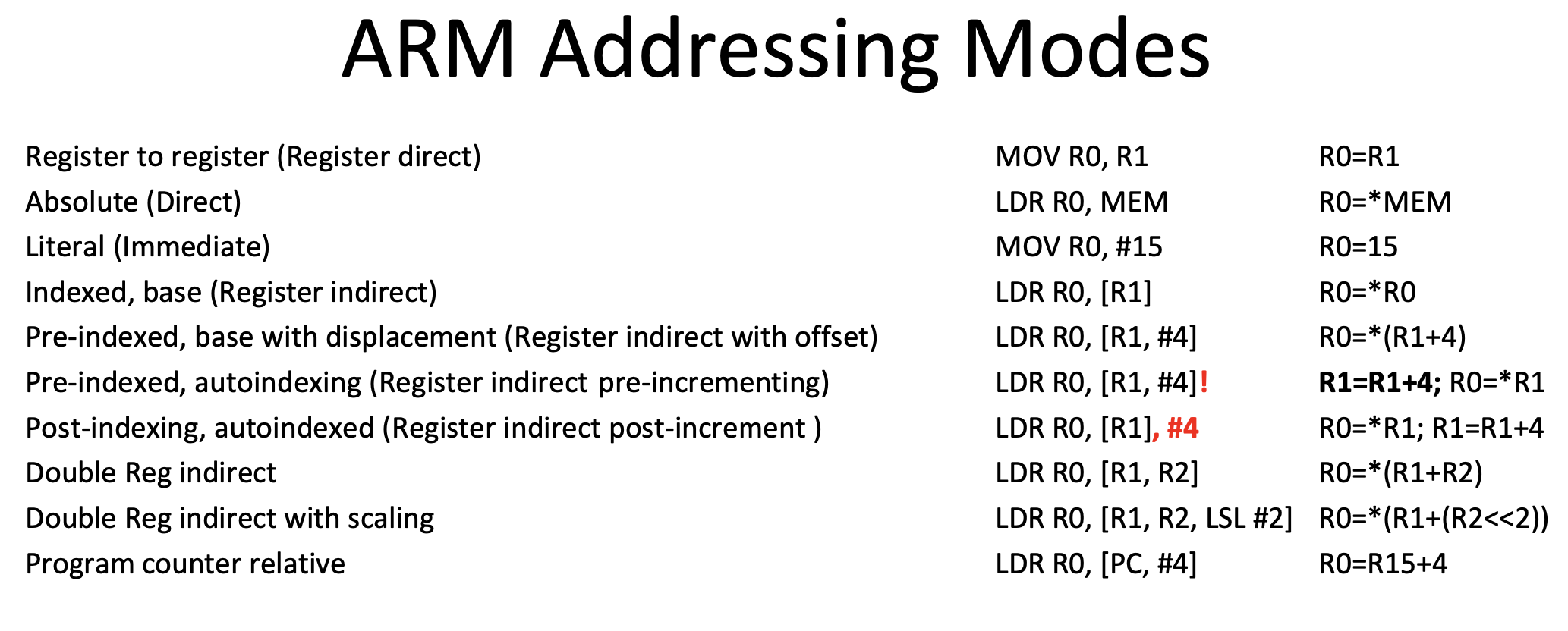
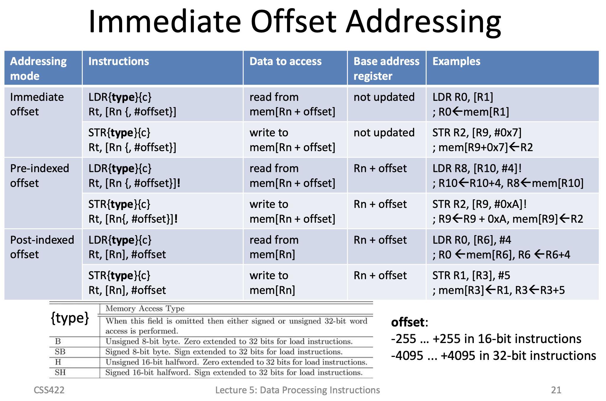
Preindex
Base Address Register is not updated
LDR R0,[R1].#4 will be Load Into Register R0, the value at address [R1+4]
Postindex
Base address register is updated by the offset
LDR R0,[R1],#4 will be Load into register R0 the value at address R1, then r1=r1+4
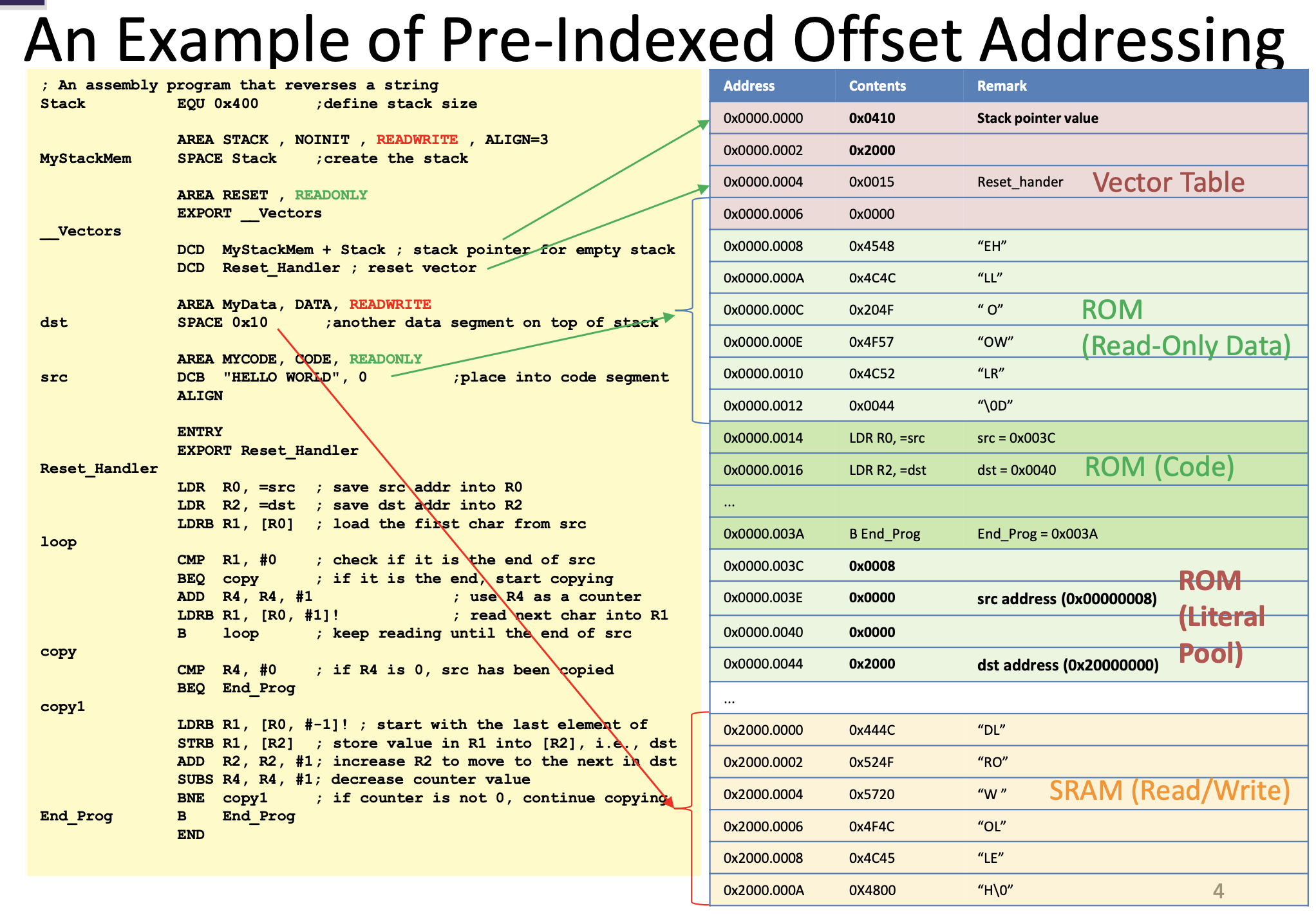
Preindex with Writeback
Base address register is updated by the offset
LDR R0,[R1,#4]! will be Load into register R0 the value at address R1+4, then r1=r1+4
Data Sizes
1 Bit is 1/0
4 bits is a nibble
8 bits is a byte - 8 bits
2 bytes is a half word - 16 bits
4 bytes is a word -32 bits
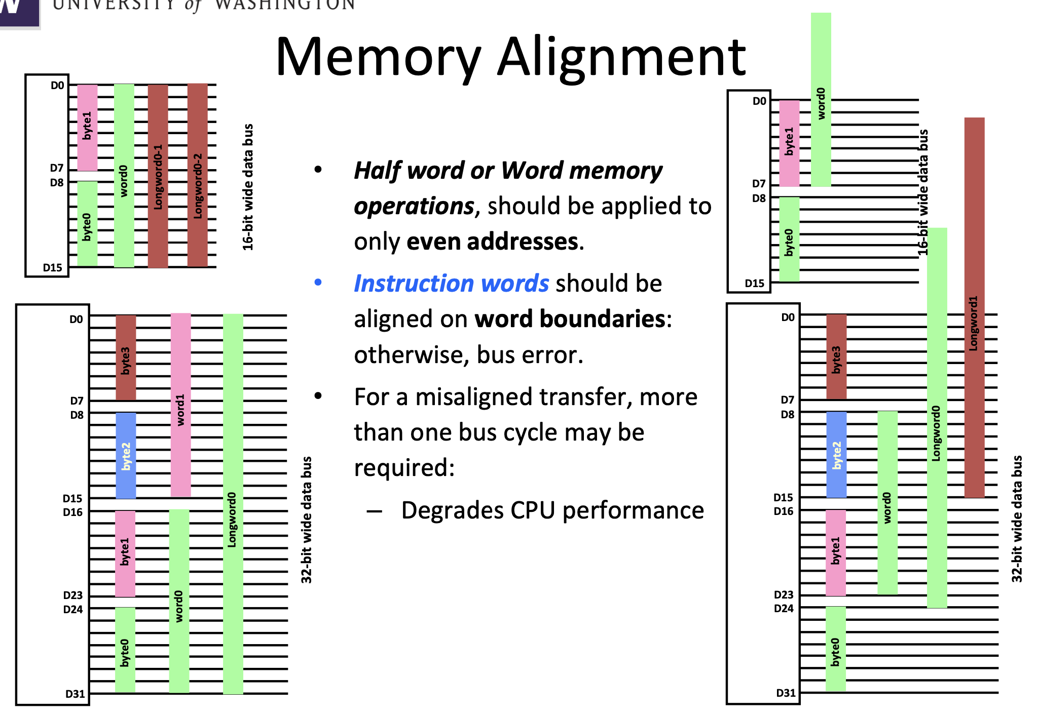
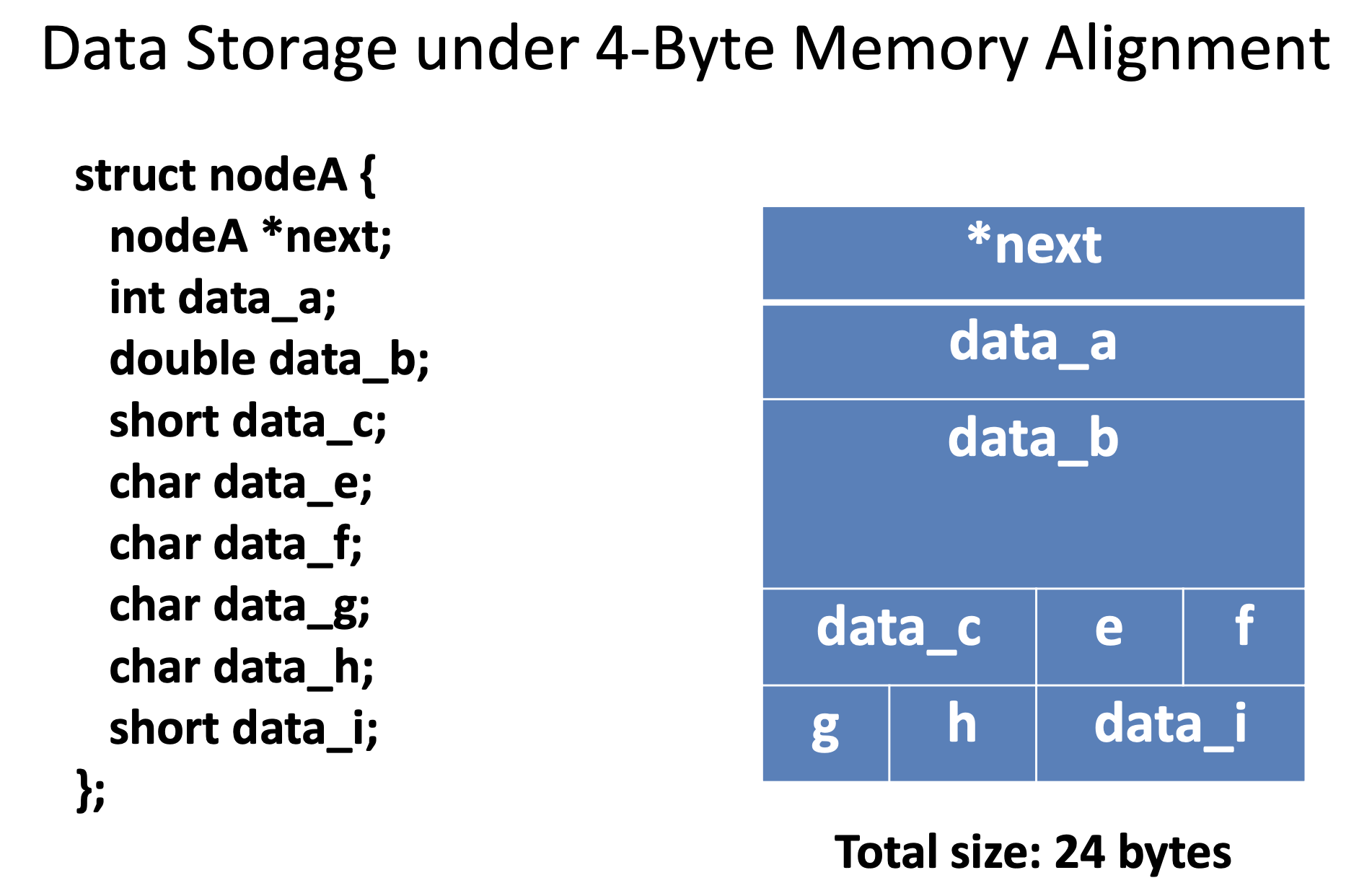
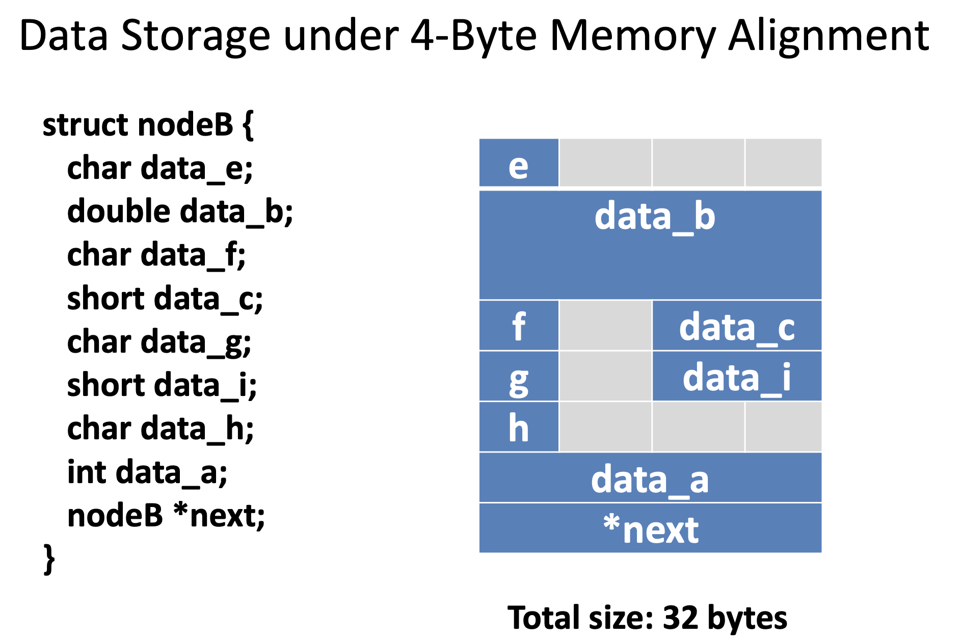
Data Alignment
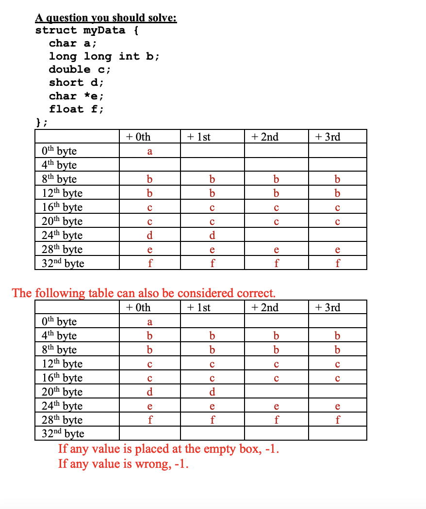
char 1 byte, byte aligned
signed char 1 byte, byte aligned
unsigned char 1 byte, byte aligned
Signed Short 2 bytes, half word alighed
Unsigned Short 2 bytes, half word aligned
Signed Int 4 Bytes, word aligned
Unsigned Int 4 Bytes, word aligned
Signed Long 4 bytes, word aligned
Unsinged Long 4 bytes, word aligned
Signed Long Long 8 bytes, double word aligned
Unsigned Long Long 8 bytes double word aligned
Float 4 bytes, word aligned
Double 8 bytes, double word aligned
Long Double 8 bytes, double word aligned
All Pointers 4 bytes, word aligned
- Byte Data can go ay any address
- Halfword Data must be half-word aligned (address must be even numbers) 2 bytes Half word addresses end in an even hex (0,2,4,6,8,A,C,E) or, the last bit in binary ends in 0.
- Word data must be word aligned (4 bytes) or address must be divisable by 4 4 bytes In hex, addresses that are divisable by 4 end in 0,4,8, or C. In Binary, the last two bits are always 0
- Doubleword must be doubleword asligned (addresses must be divisiable by 8) 8 bytes In Hex, the address must end in 0 or 8, In binary, the last three bits must end in 0
Byte Ordering
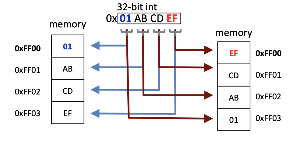
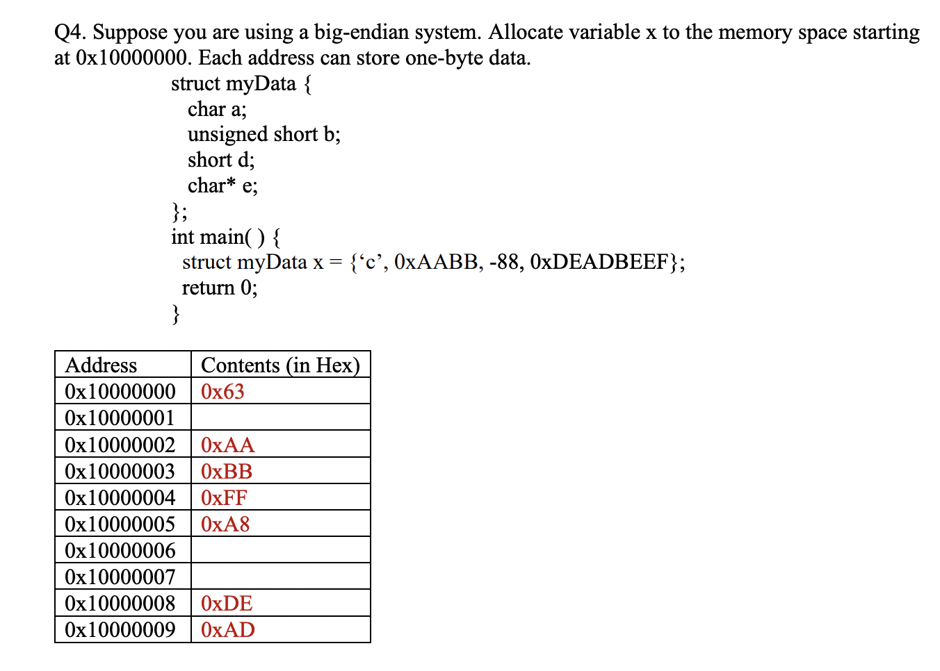
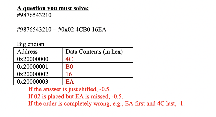
lets say you have a 32 bit integer value 0x01234567
-
Big Endian
this stores the values from MSB to LSB or 01,23,45,67 in increasing memory order (102,103,104) etc. -
Little Endian
This stores the values from LSB to MSB or 67, 45, 23,01 in increasing memory values (102,103,104) etc
The address in memory is always the address of the lowest address
Stack Information
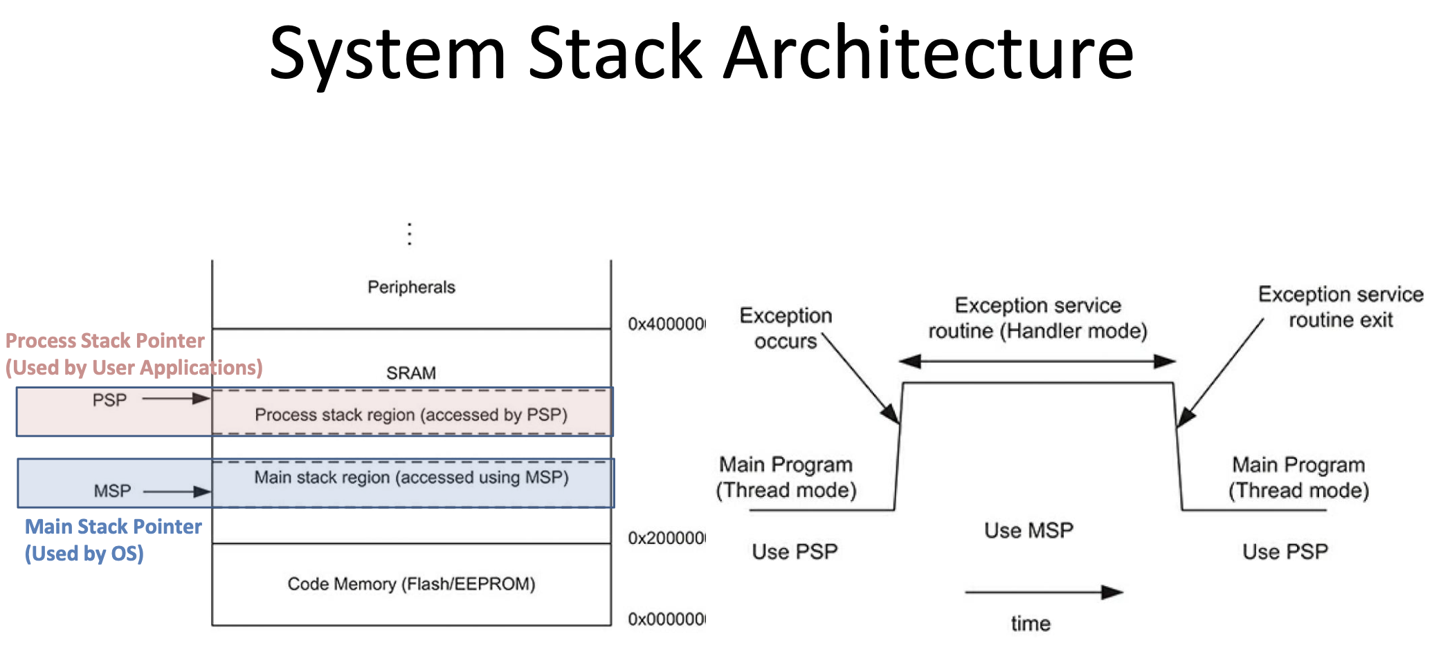
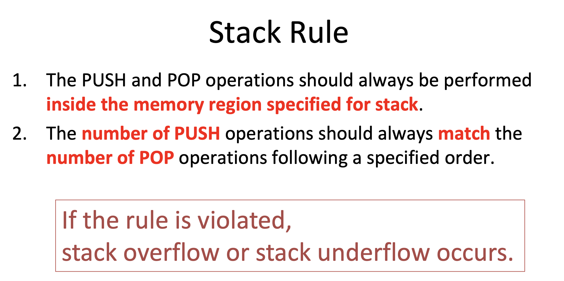
The Stack is a reserved portion of memory for temporary storage of register values.
The Stack Pointer is an address register who's purpose is to refer to the top of a stack
The stack can grow in two ways:
- Increment - ascending through addresses in memory - every time you add a register you add to the address
- Decrementing - every time you put a new value on, you're growing to a lower memory address
You can increment/decrement in different ways as well
- Pre increment - the sp points to the current location and updates the sp before writing a value to the stack
- Post Increment - the stack pointer points to the next place to store something
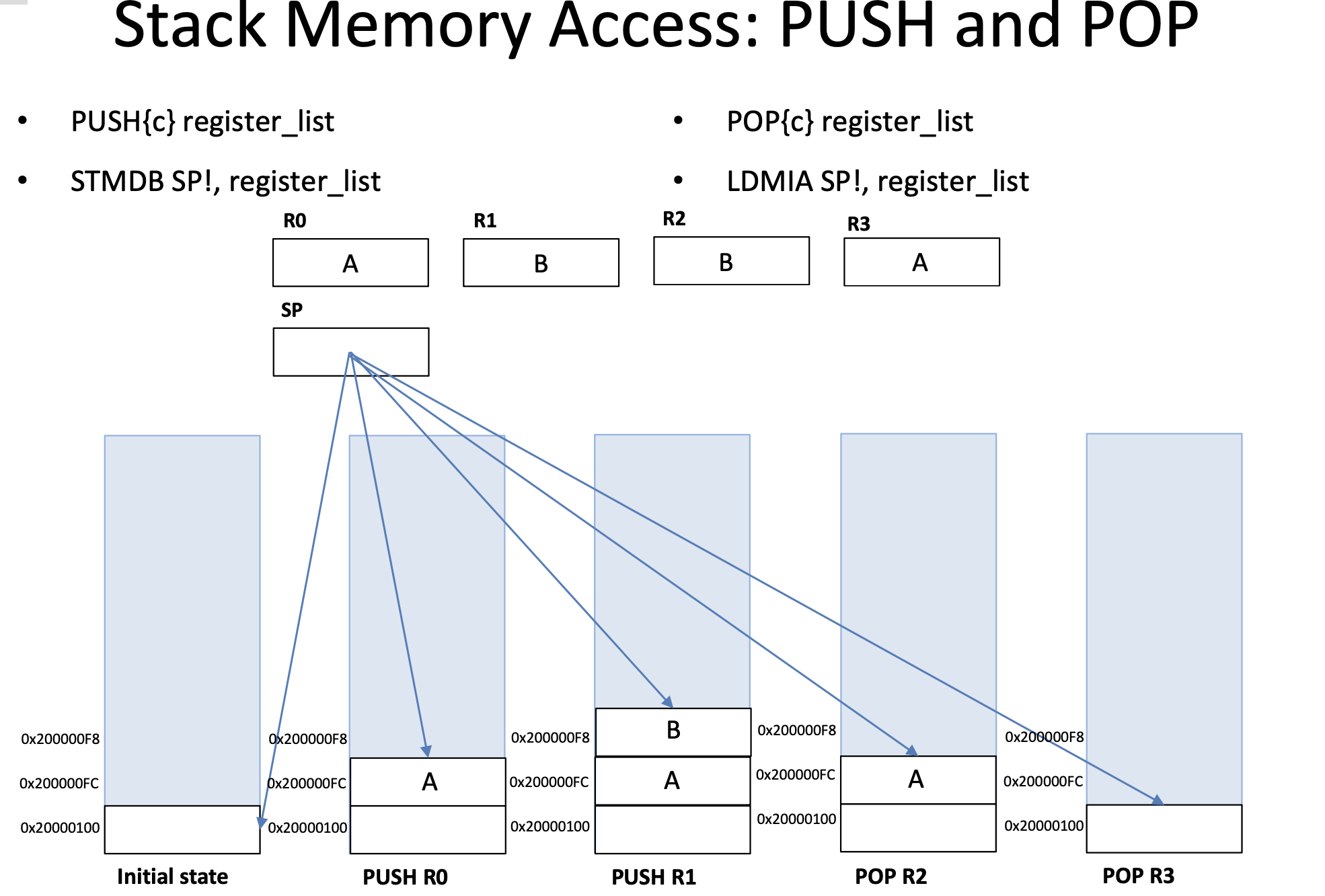
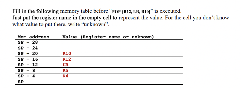
The two primary opcodes for dealing with the stack/stack pointer are push and pop.
The Stack works in a LIFO (Last in First Out) method. In ARM, the Stack decreases towards 0, so if you started at 1000 and added an item to the stack, the stack pointer moves down in memory. Everytime we push onto the stack, we're pushing 32 bits. R13 typically acts as the stack pointer register
We decrement the pointer before we write the new value. This means that SP always points to the last value pushed to the stack.
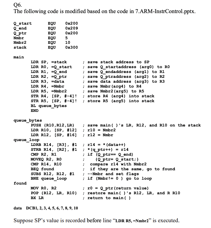
STR R0, [SP,#-4]! take the stack pointer, decrement by 4, update the stack pointer to that address, and store R0 in that address.
LDR R0,[SP], #4 will pop the above value off the stack
You can use tabs to indicate positions to help track what's been pushed
The two primary opcodes for dealing with the stack/stack pointer are push and pop.
Push will store a register to the stack.
Pop removes a register from the stack
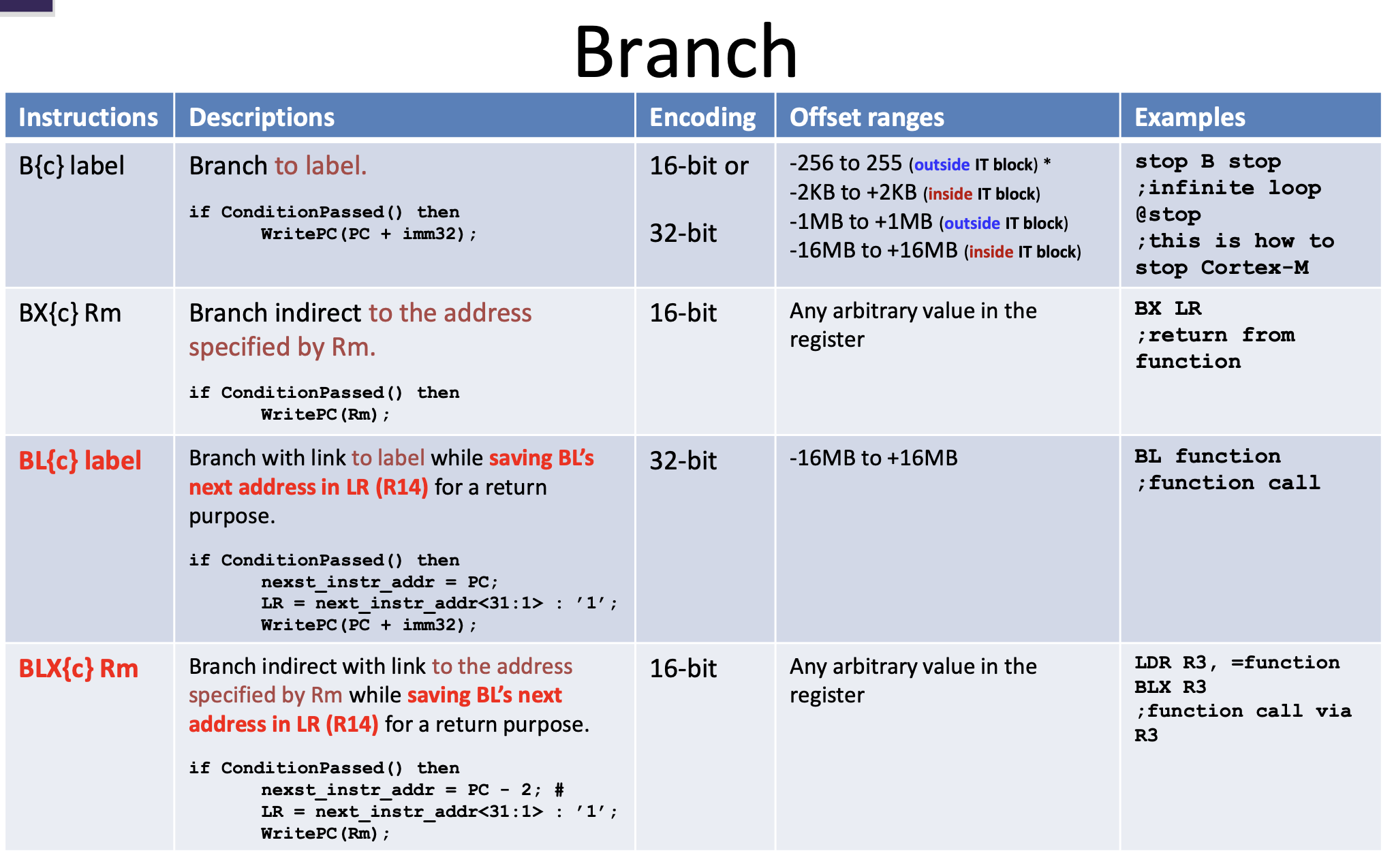
Link Register
Stores a return address
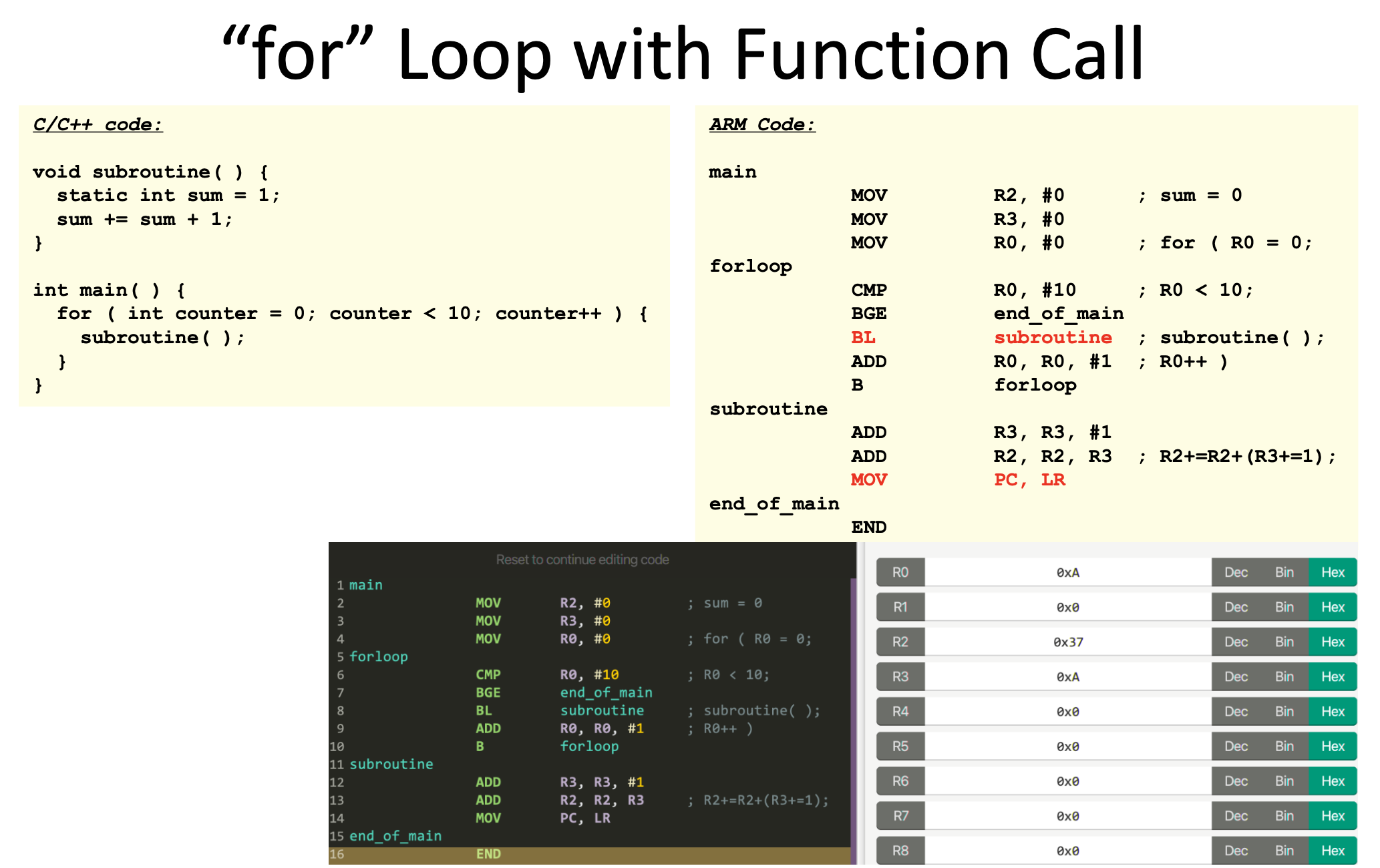
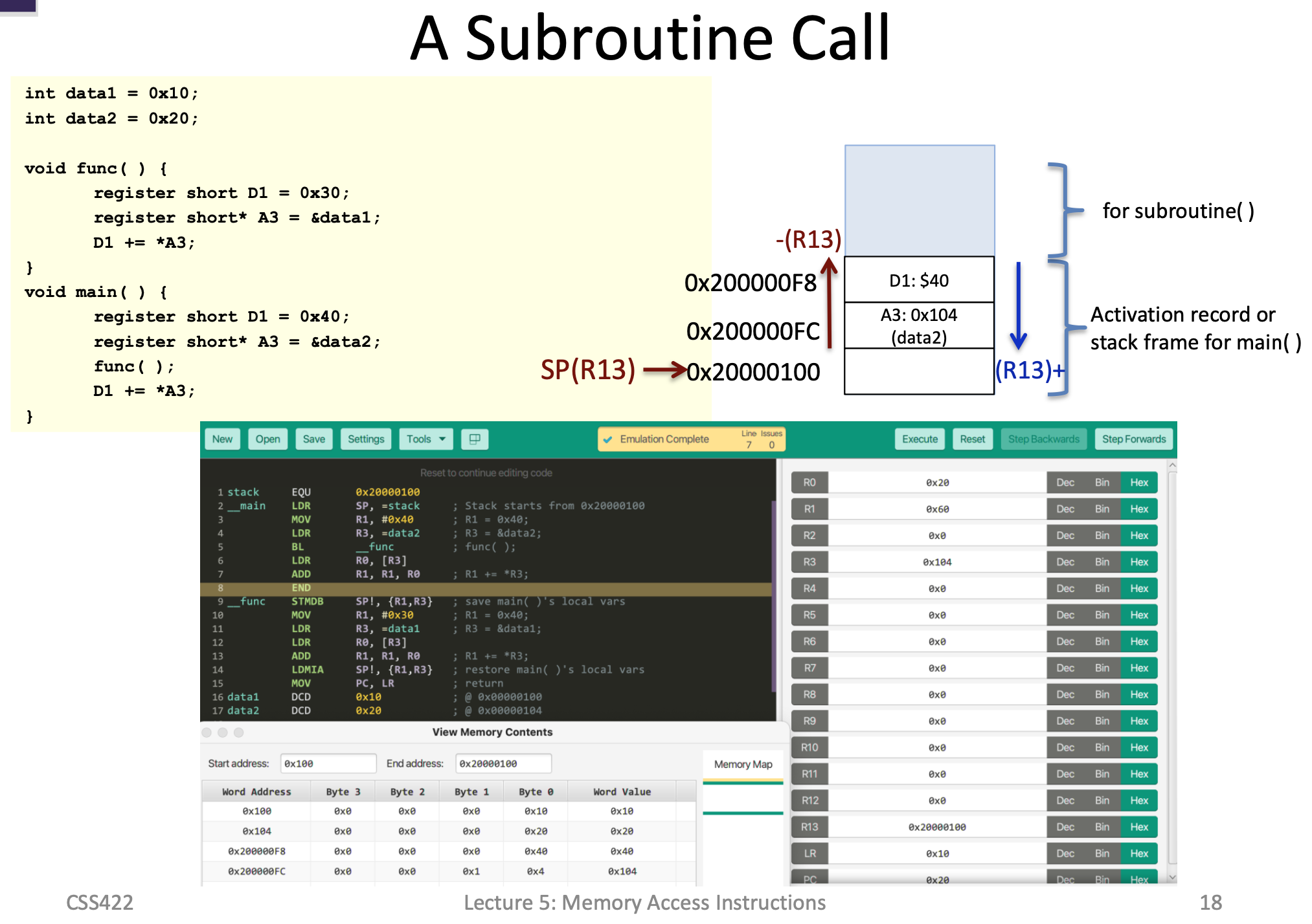
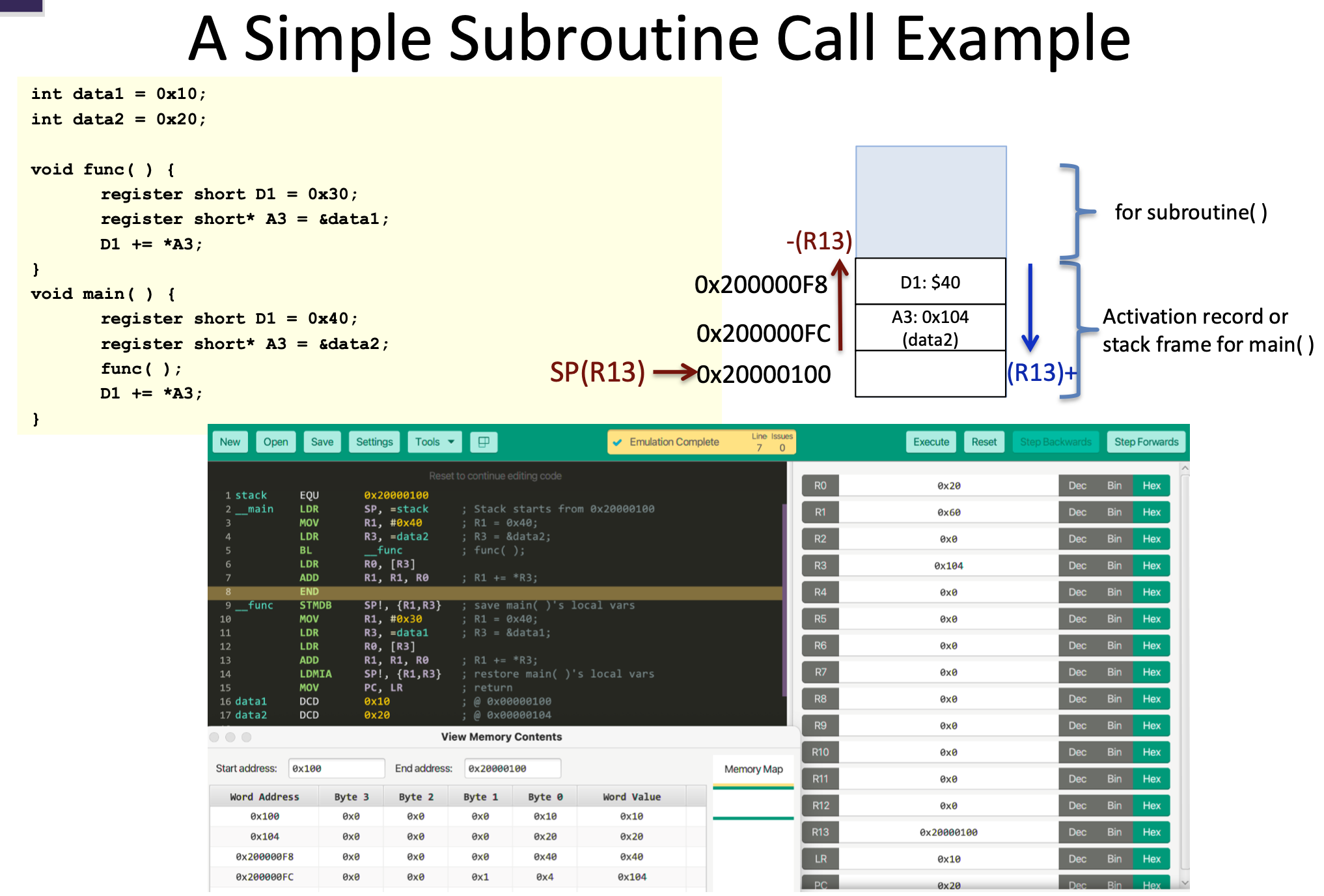
Uses of the stack with Functions
You can use the stack to track previous link register values (return addresses)
Program Counter
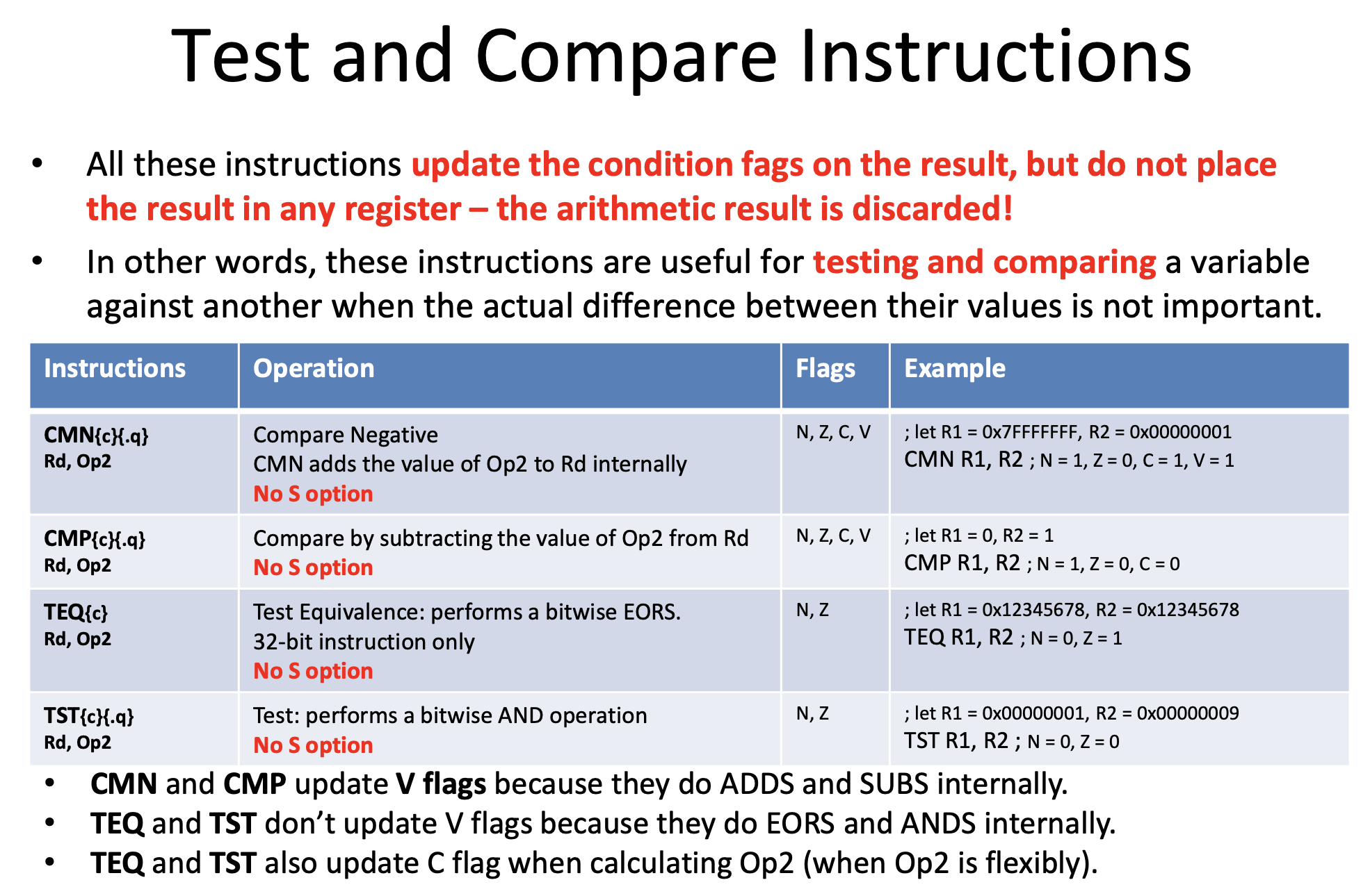
CMP
A compare can be thought of as a "virtual subtract" . No value is stored, but the flags are updated. When you do a CMP, the primary flags you are looking at are the Z flag and the N flag
If (a == b) Z flag will be 1, N flag will be 0 (1 and 0)
If (a < b) Z flag will be 0, N flag will be 1 (0 and 1)
If (a > b) Z flag will be 0, N flag will be 0 (0 and 0)
If (a != b), Z flag will be 0, (0 or X)
If (a>= b) N flag will be 0 (x or 0)
If (a <=b )(1 or 1)
Useful Commands
Useful Ideas from Slides
Overflow

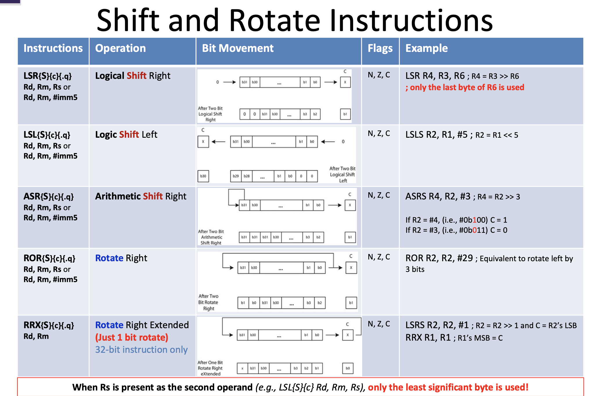
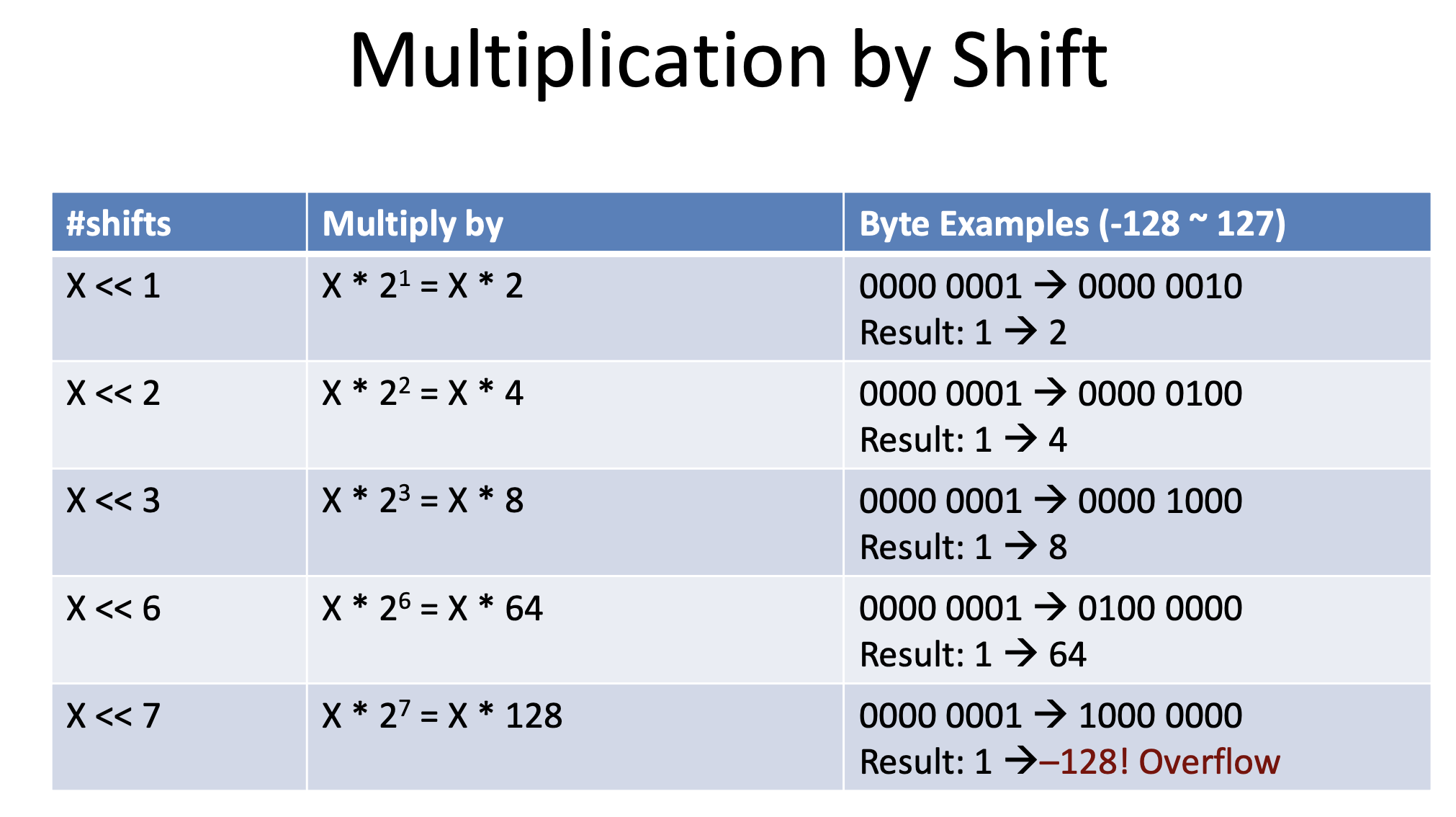
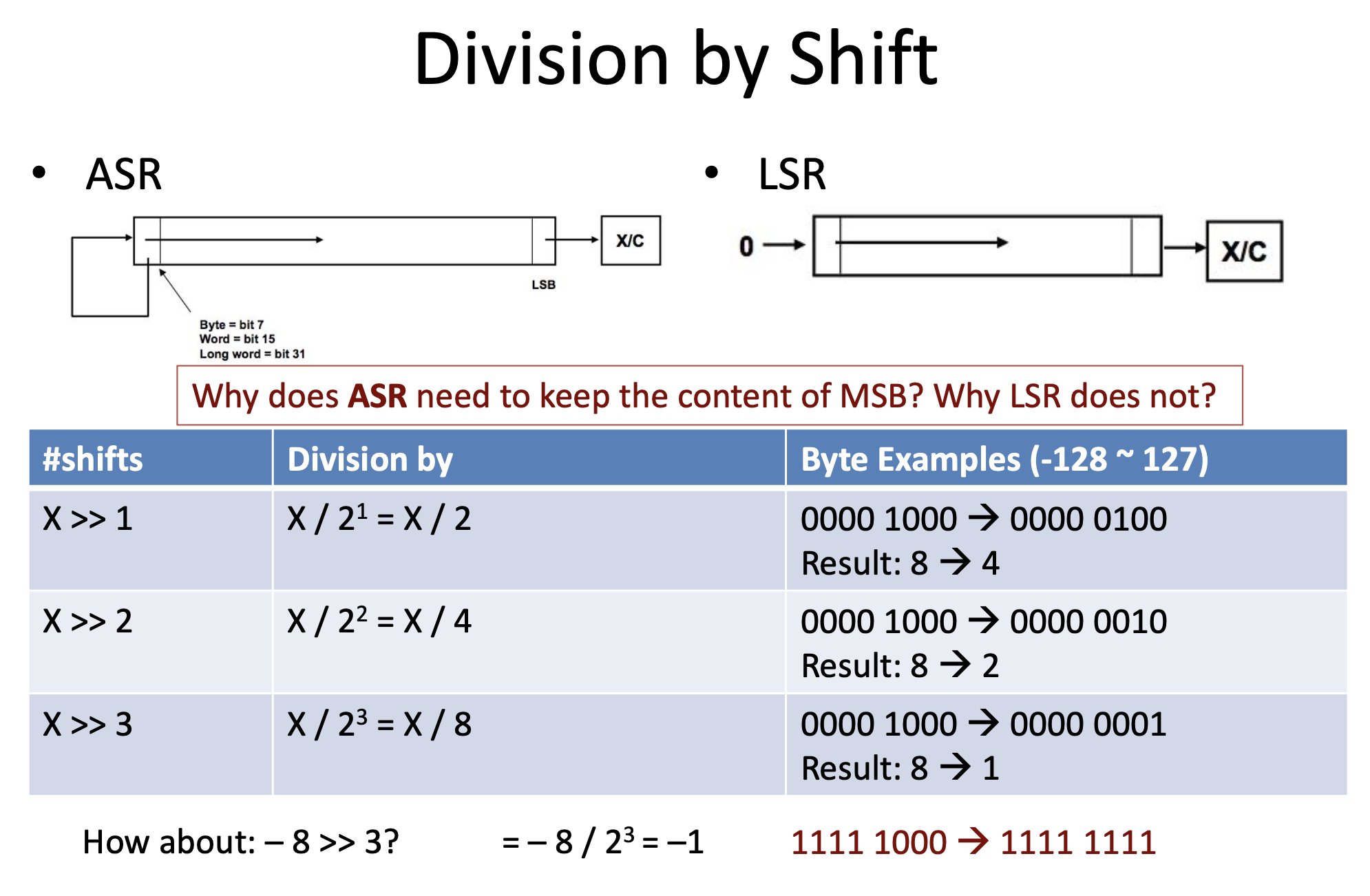
Shifting Left/Right
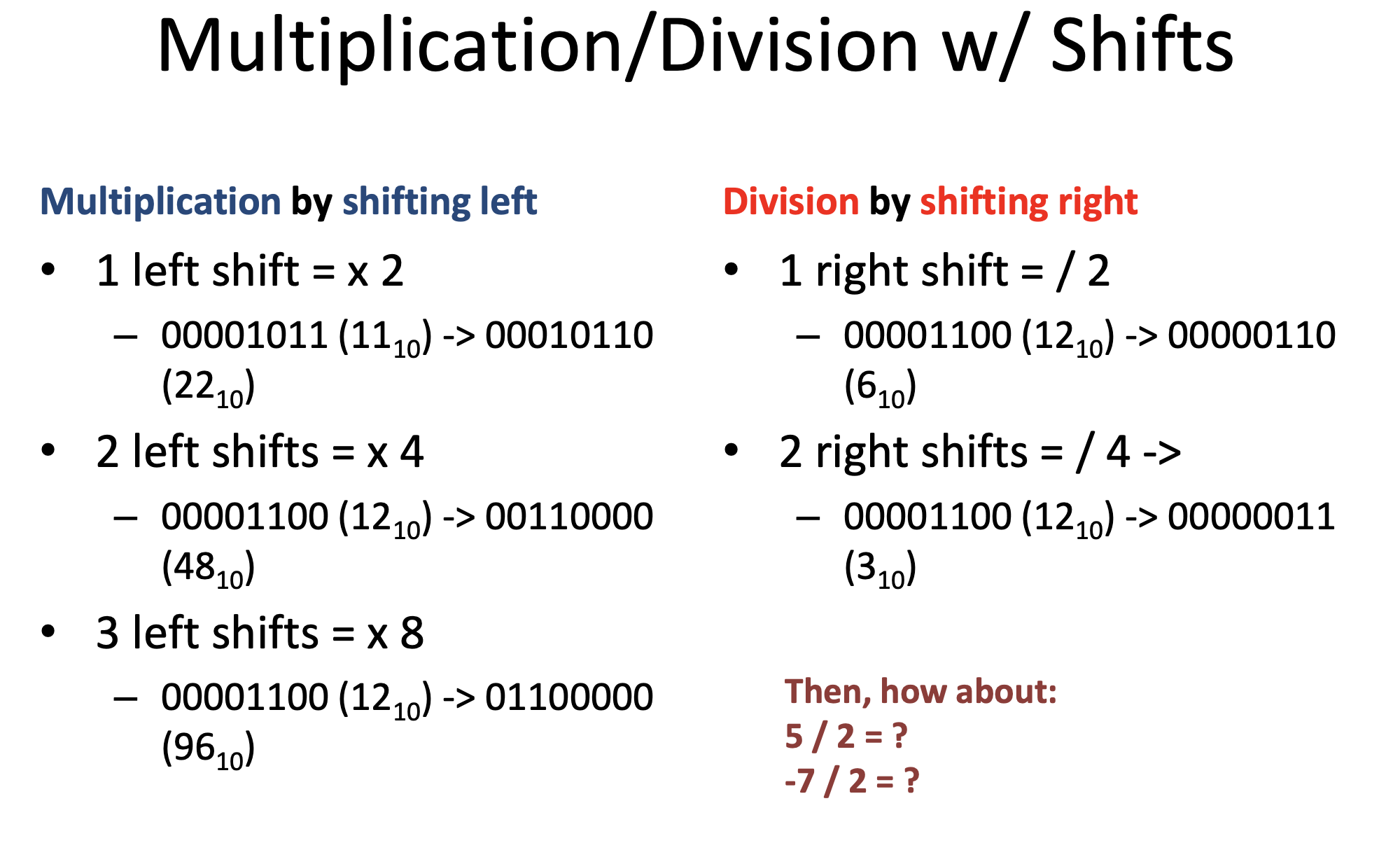
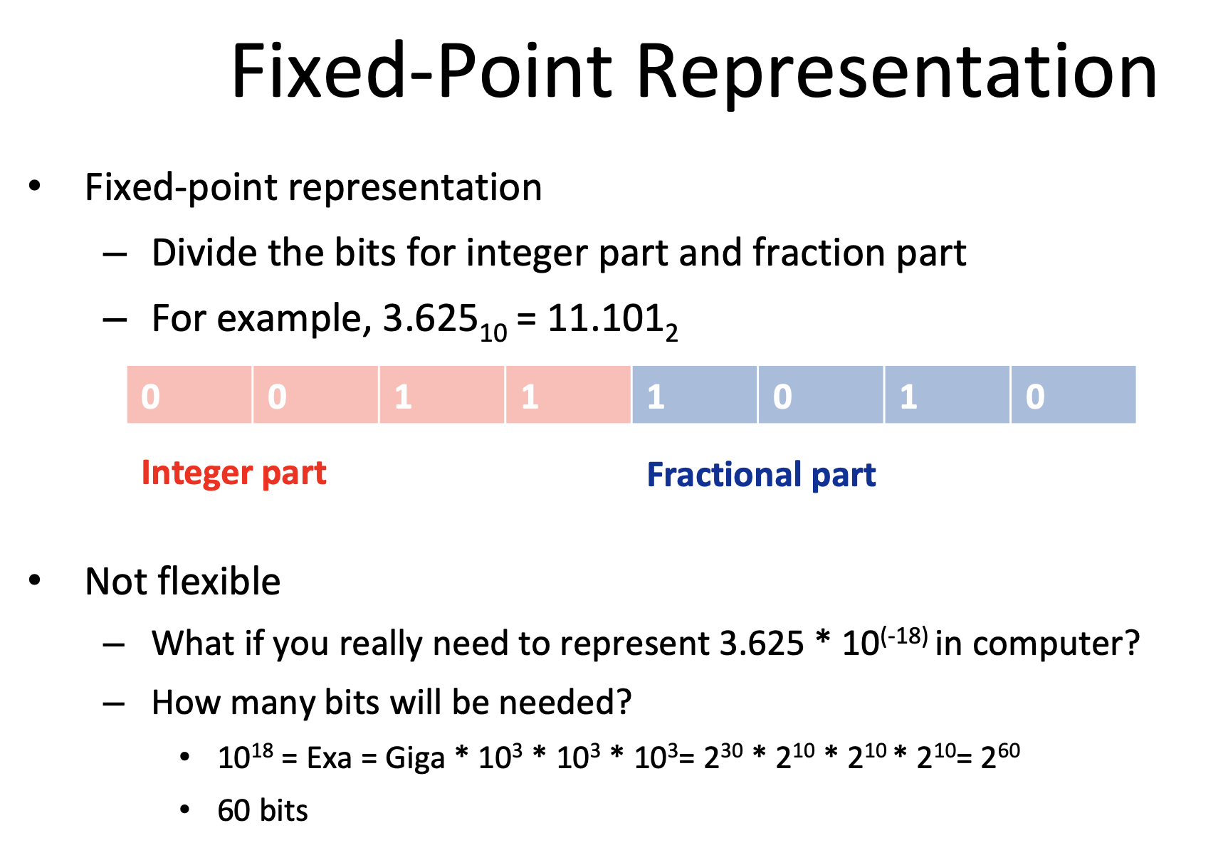
Fixed Point Representation
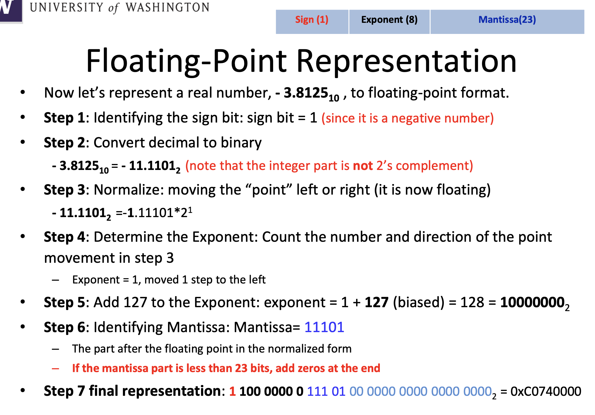
Floating Point Representation
Endianness

Alignment
Cortex M Registers
Privilege

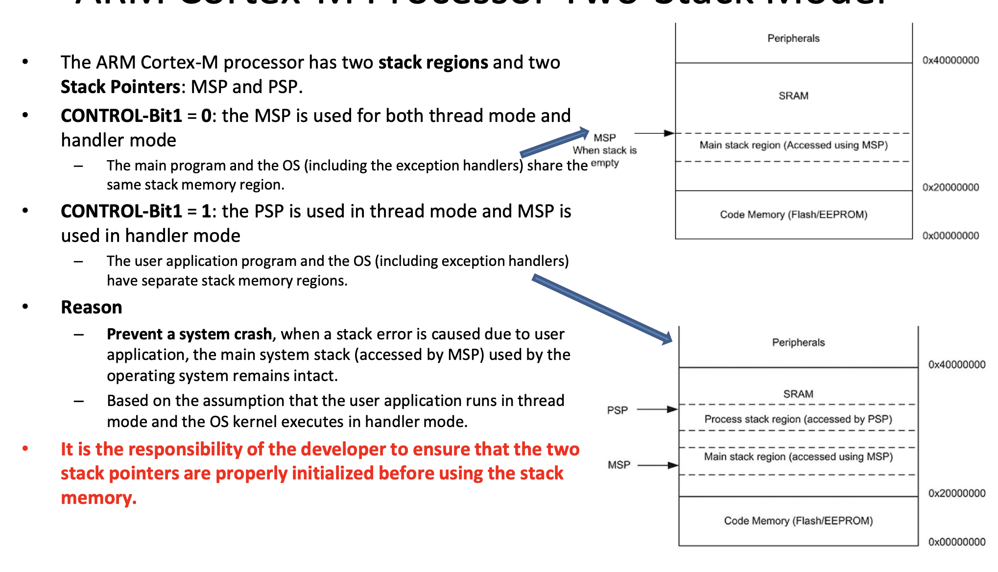
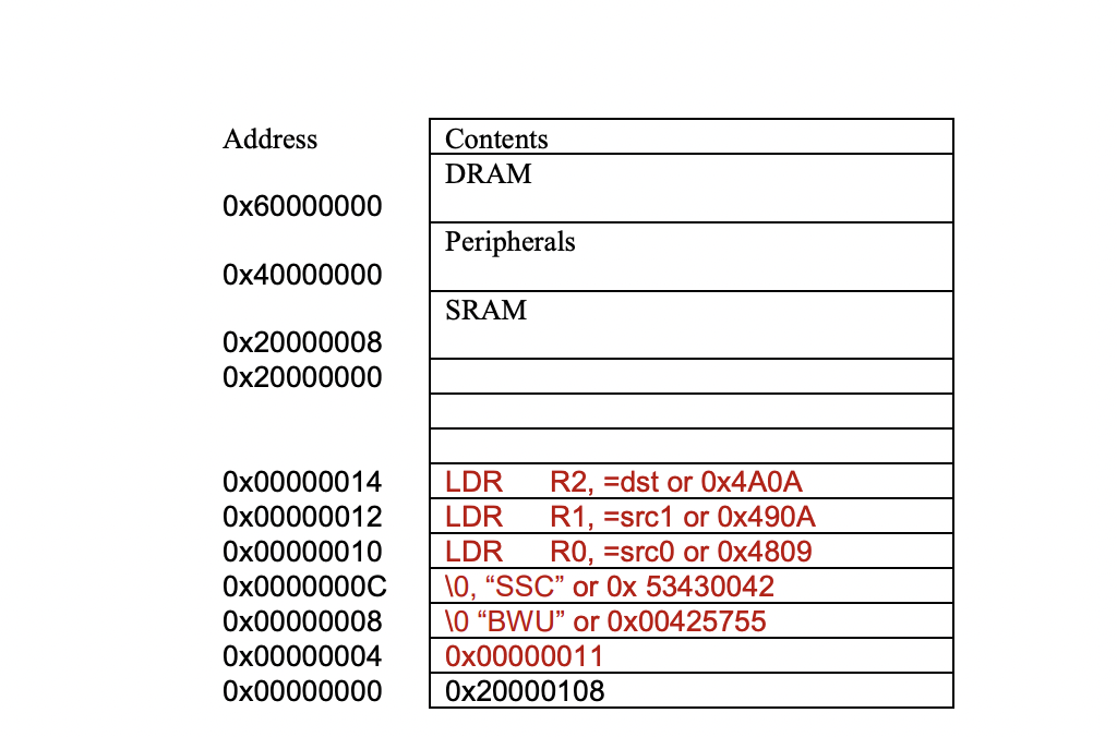
System Stack Architecture
Status Register
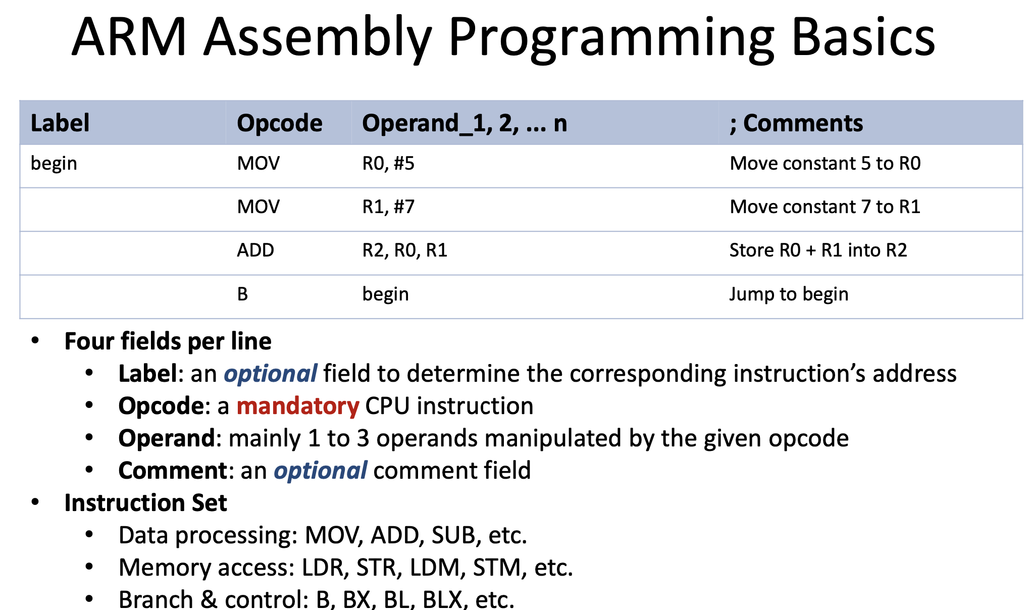
Assembly Programing Basics
Addressing Modes
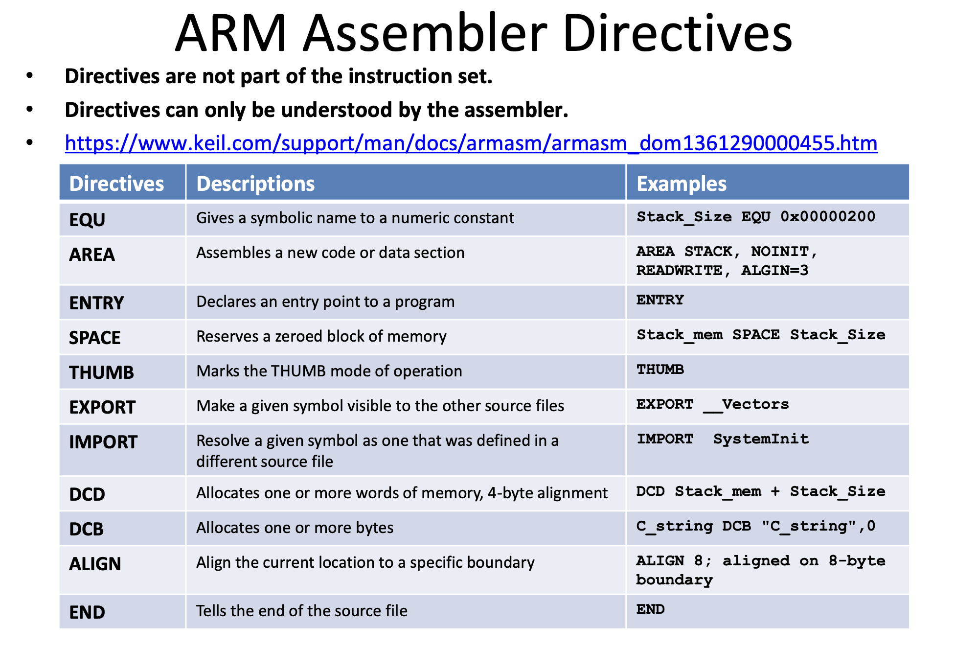
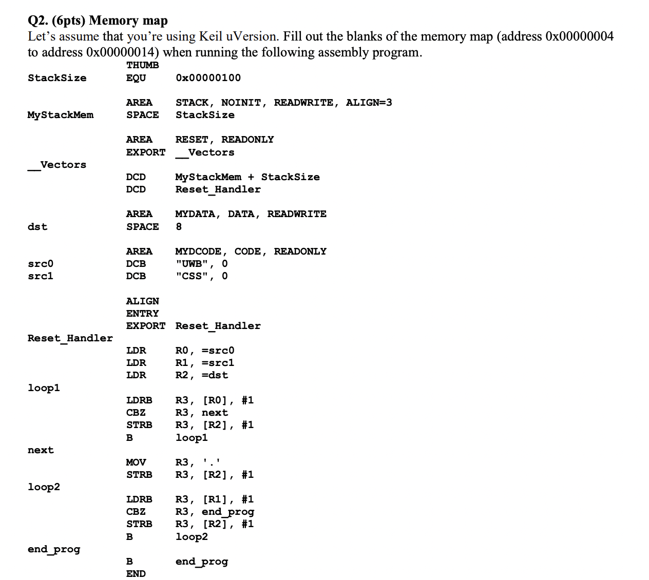
Assembler Directives
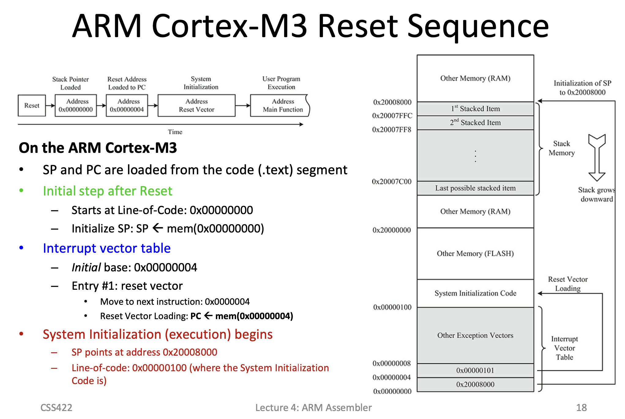
Reset Handler
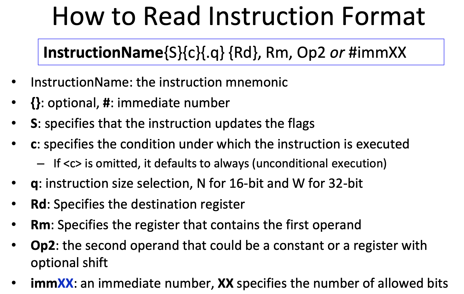
Instruction Parts
Data Movement Commands
Shift and Rotate
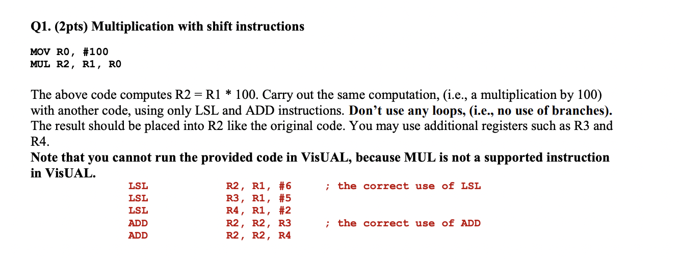
Multiplication by Shift
Division by shift
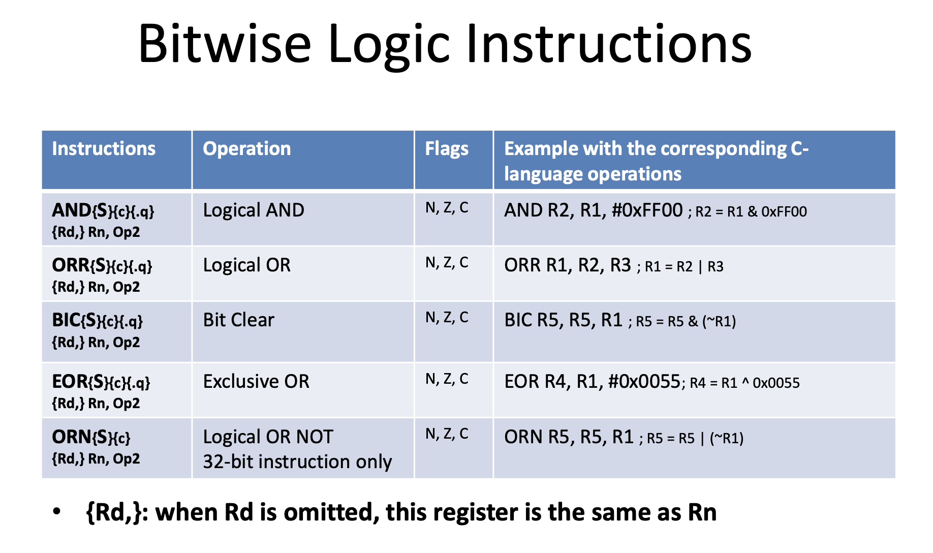
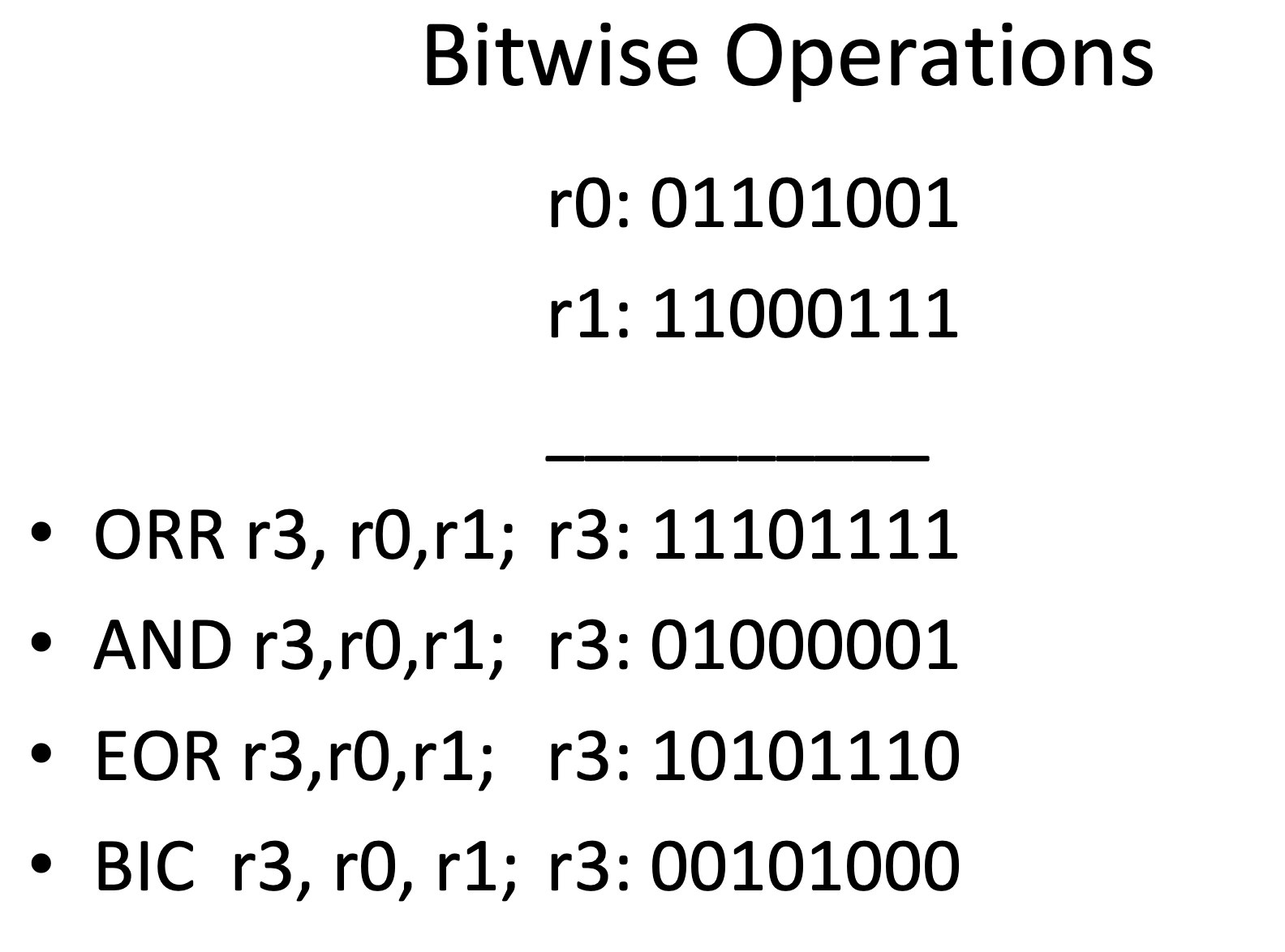
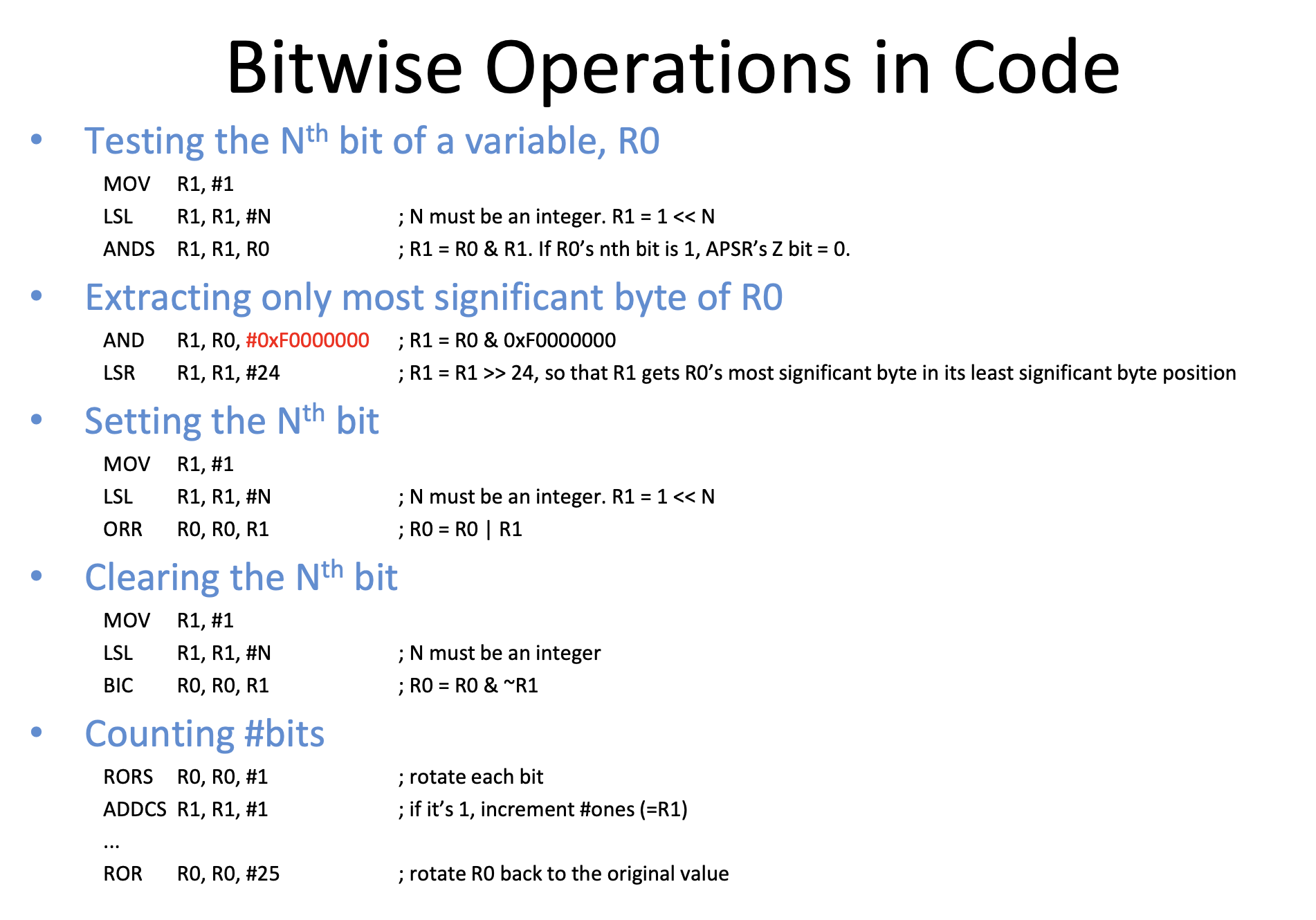
Bitwise Operations
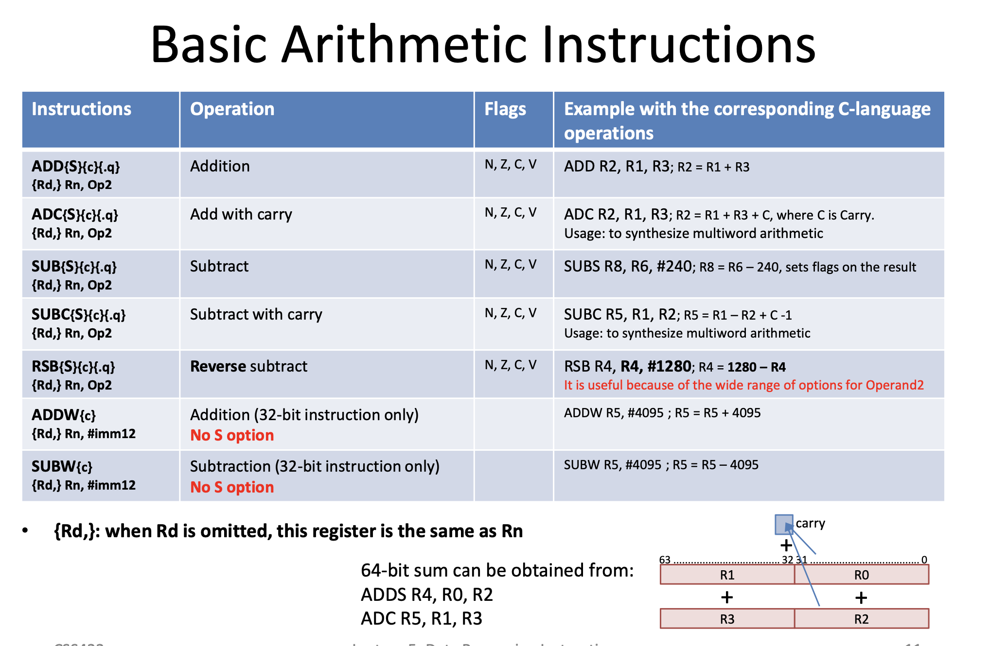
Basic Arithmetic Instructions
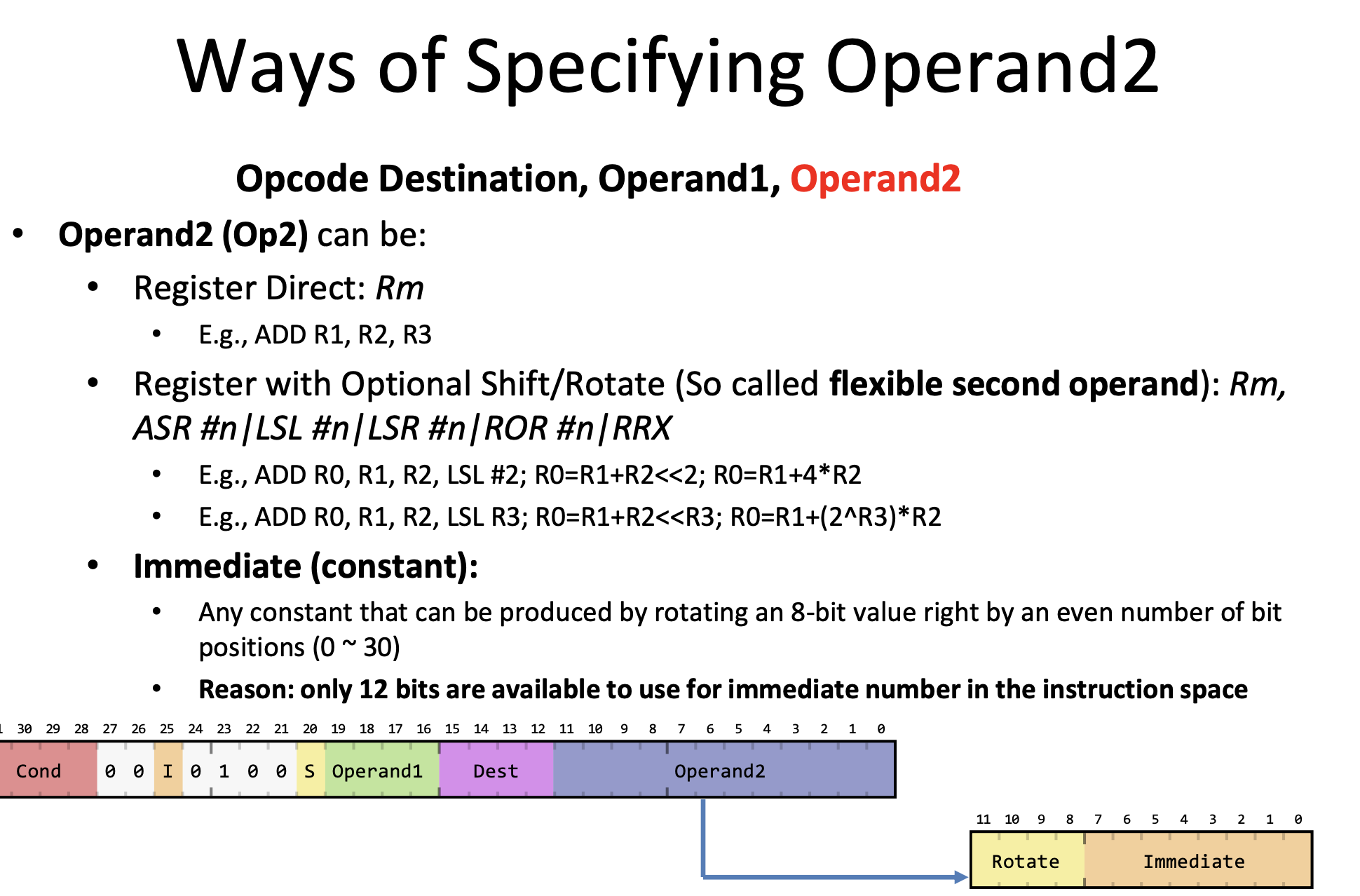
Operand 2
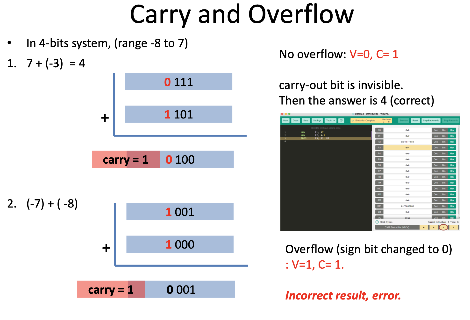
Carry and Overflow
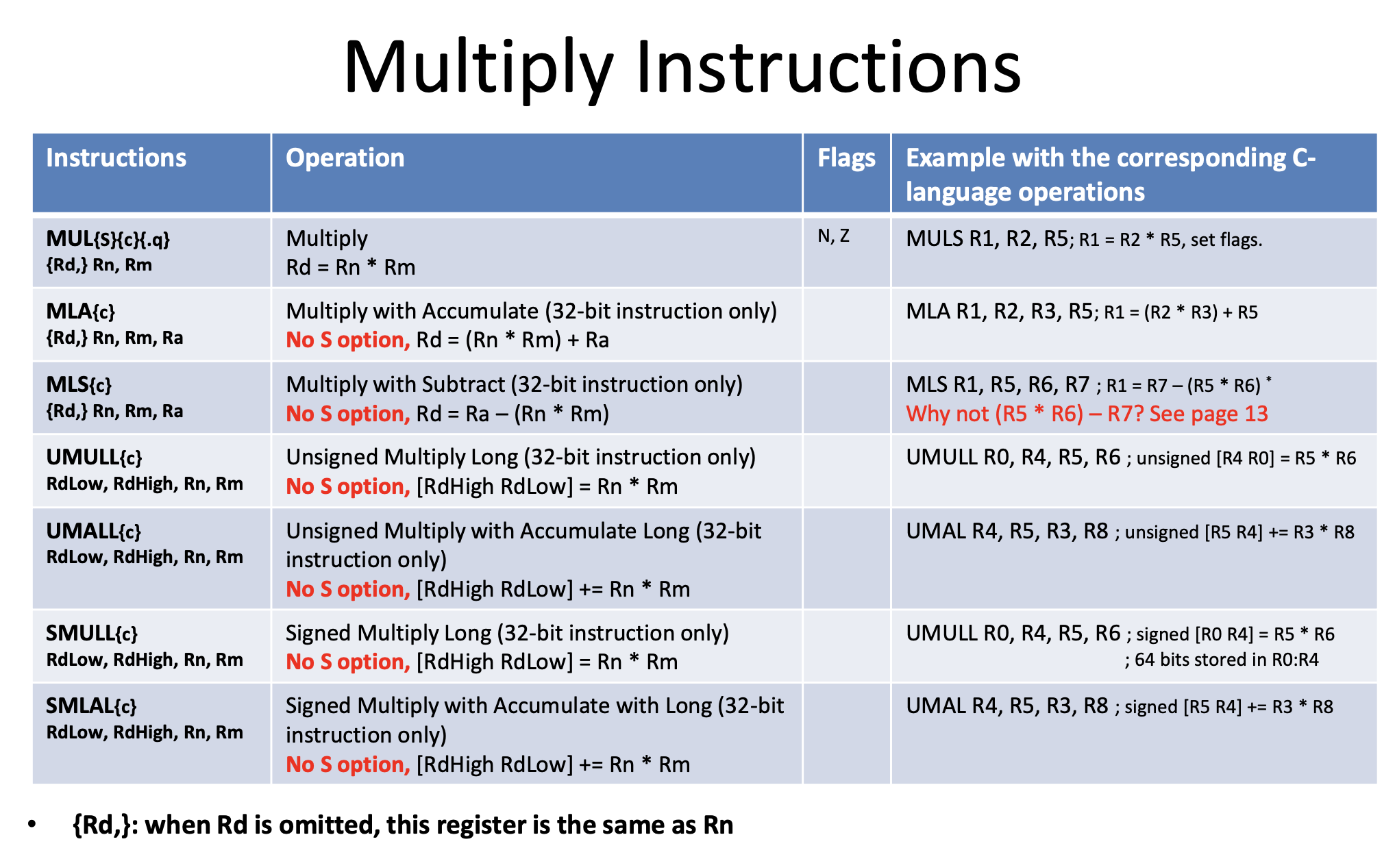
Multiply Terms
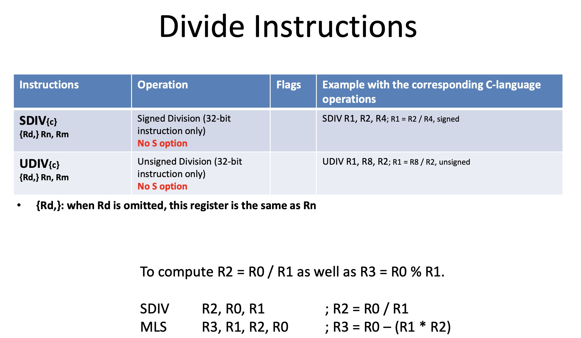
Division
Test and Compare
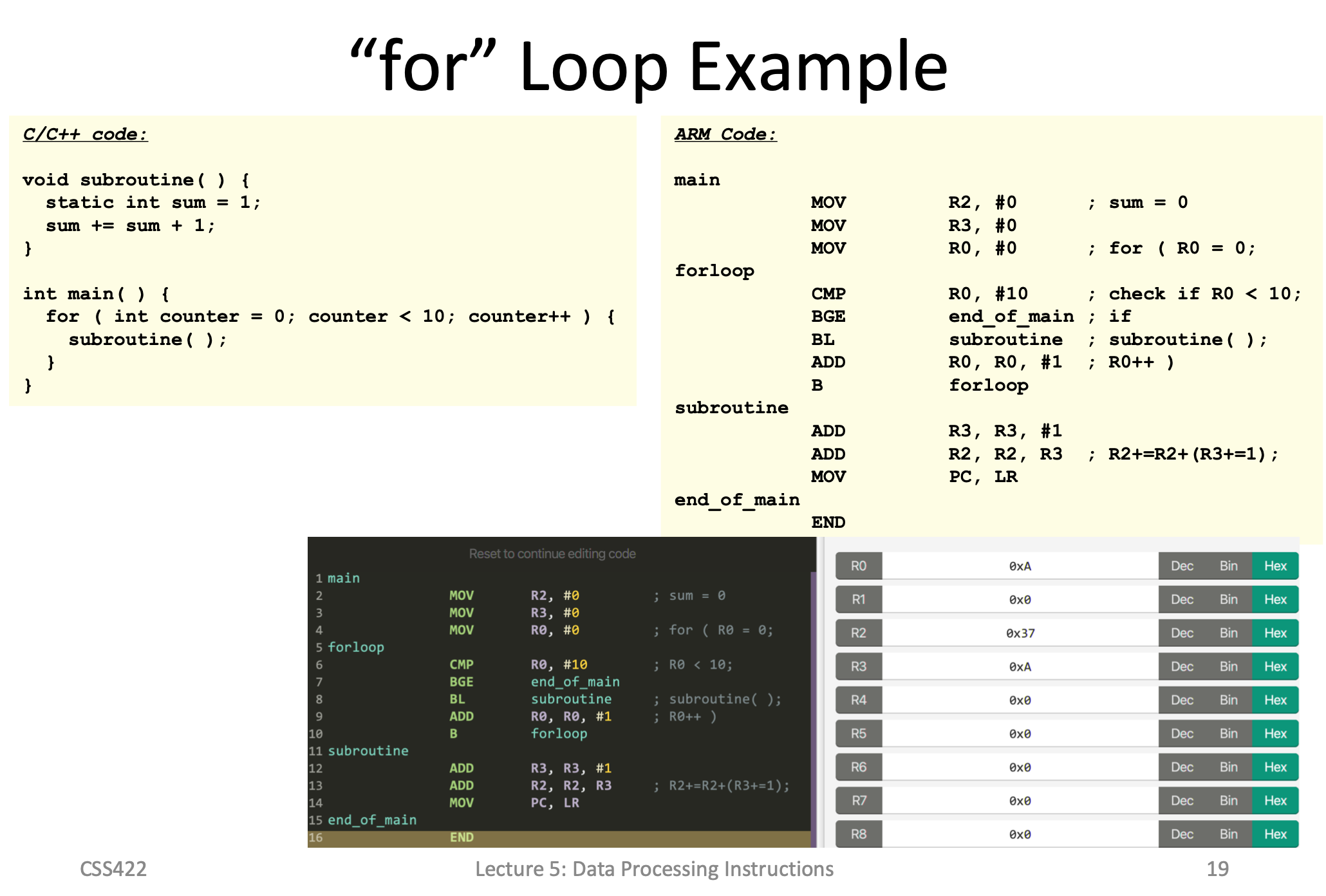
For Loop
With Function Call
Memory Access
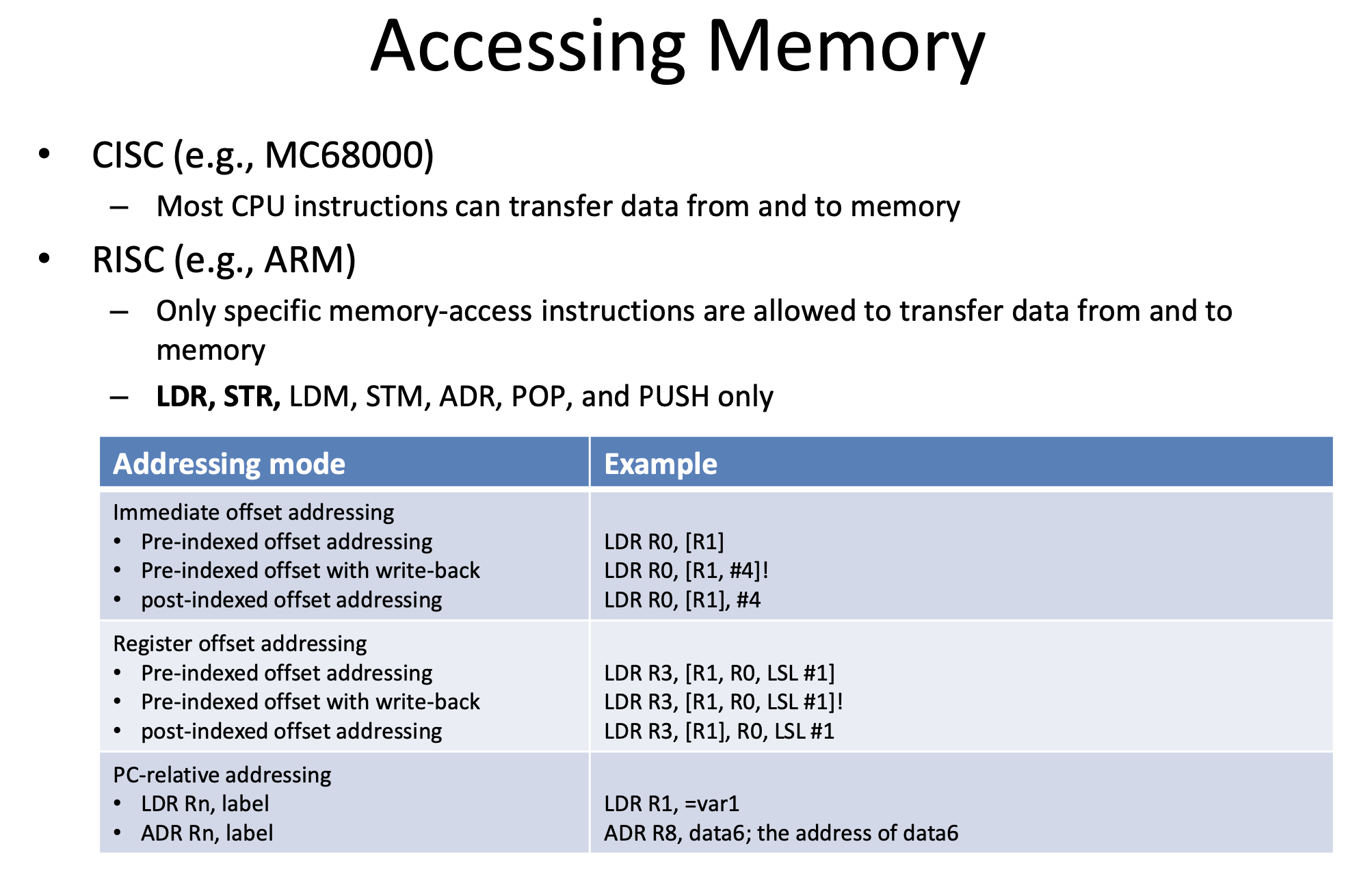
Addressing
PC Relative Addressing
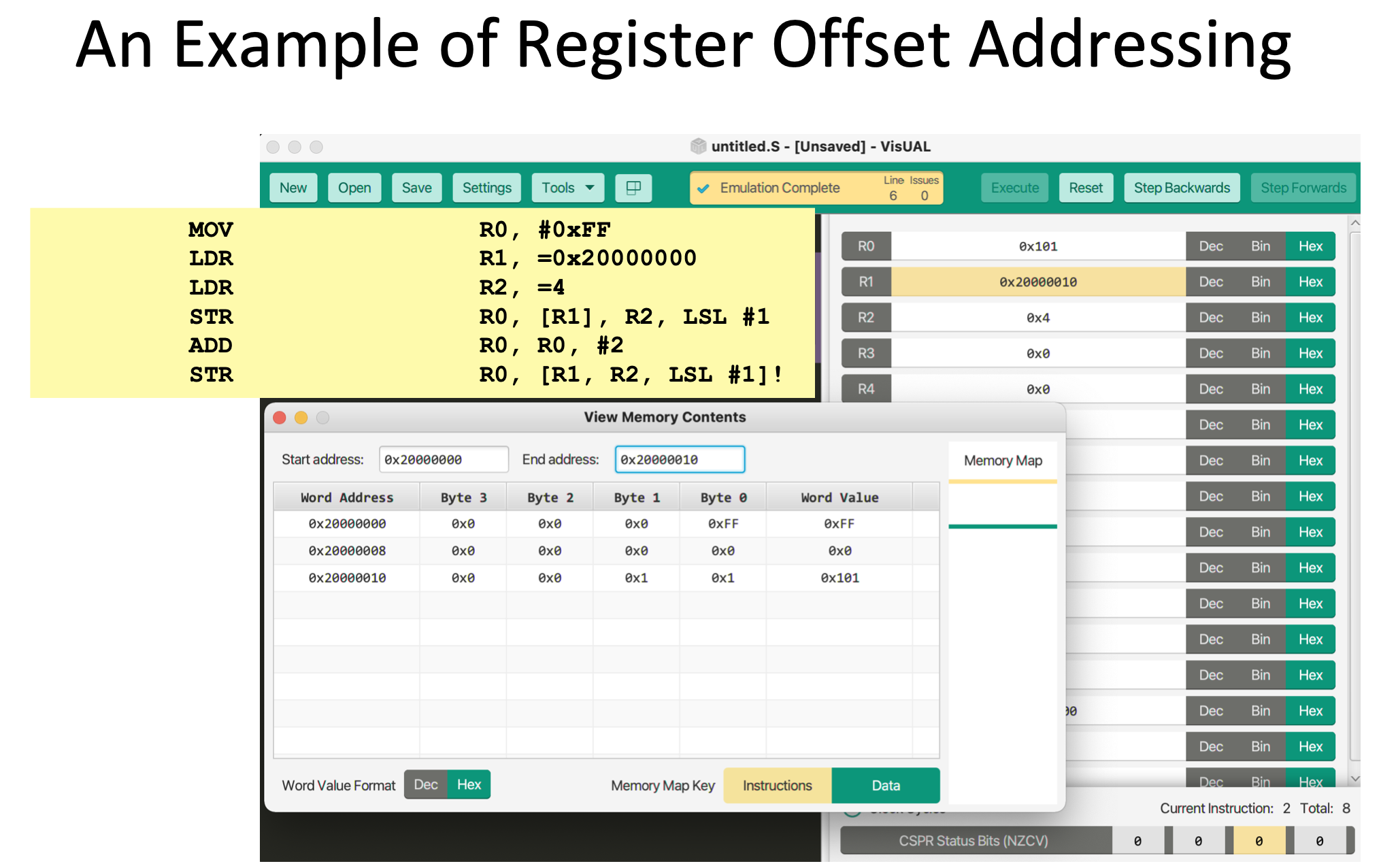
Register Offset Addressing
ASCII Table
!Pasted image 20220426202056.png
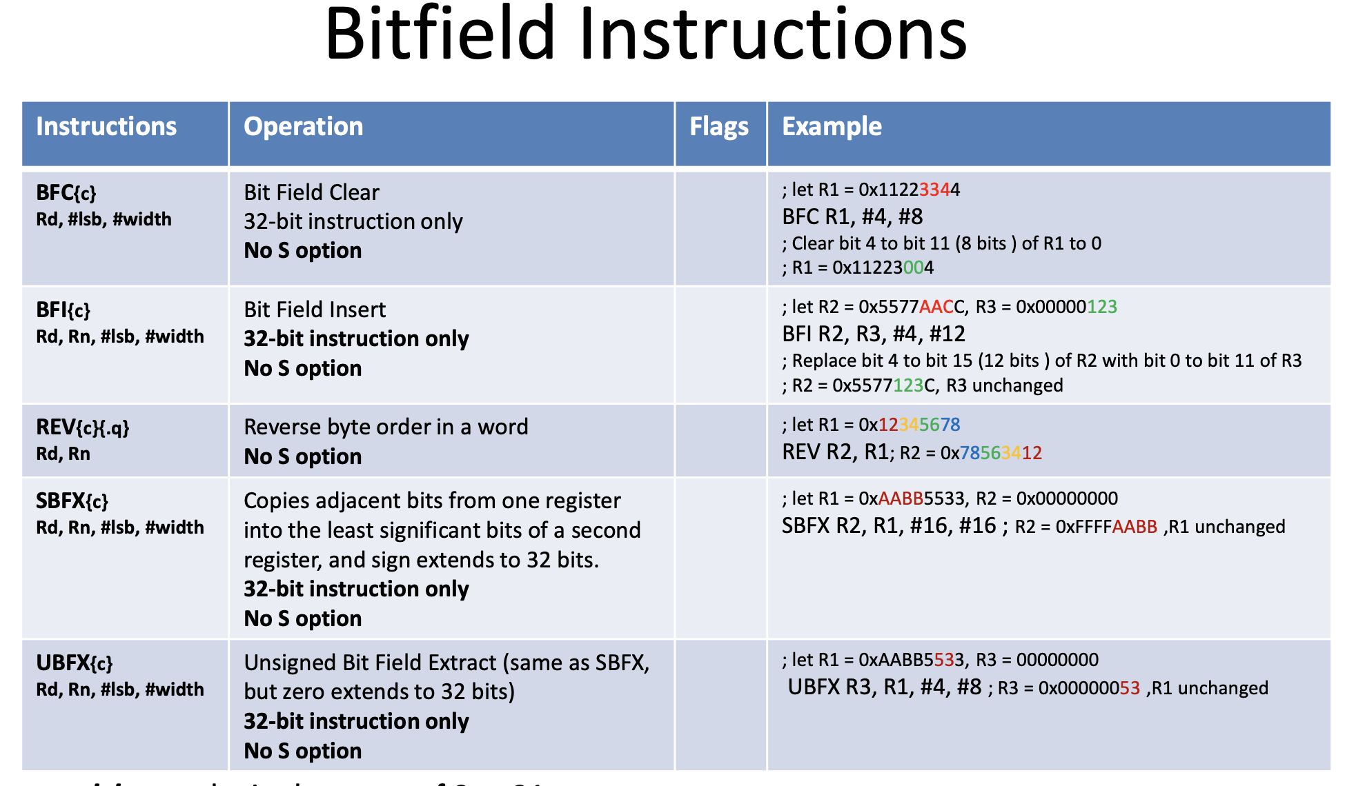
Bitfield Instructions
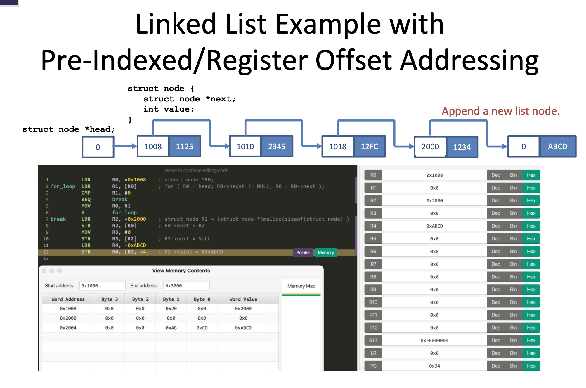
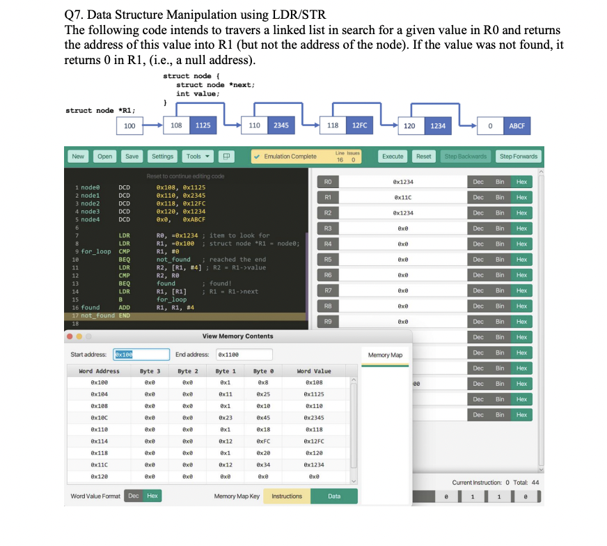
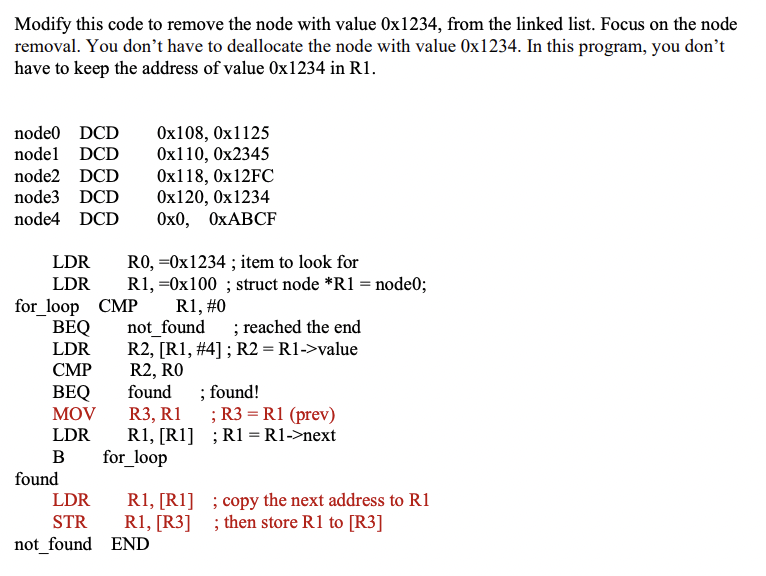
Linked List
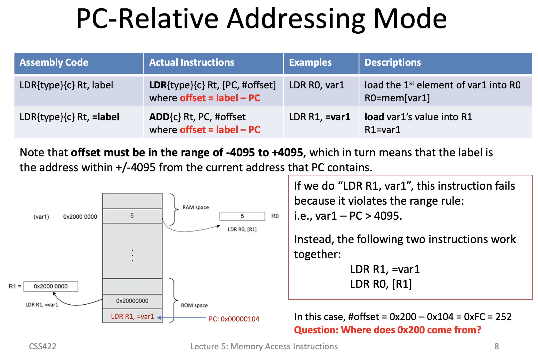
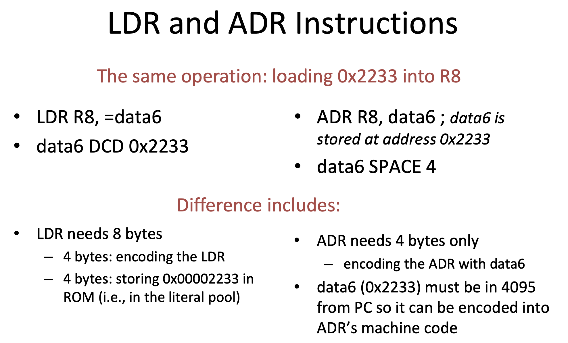
LDR/ADR
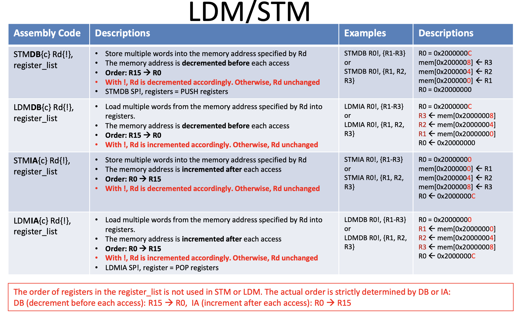
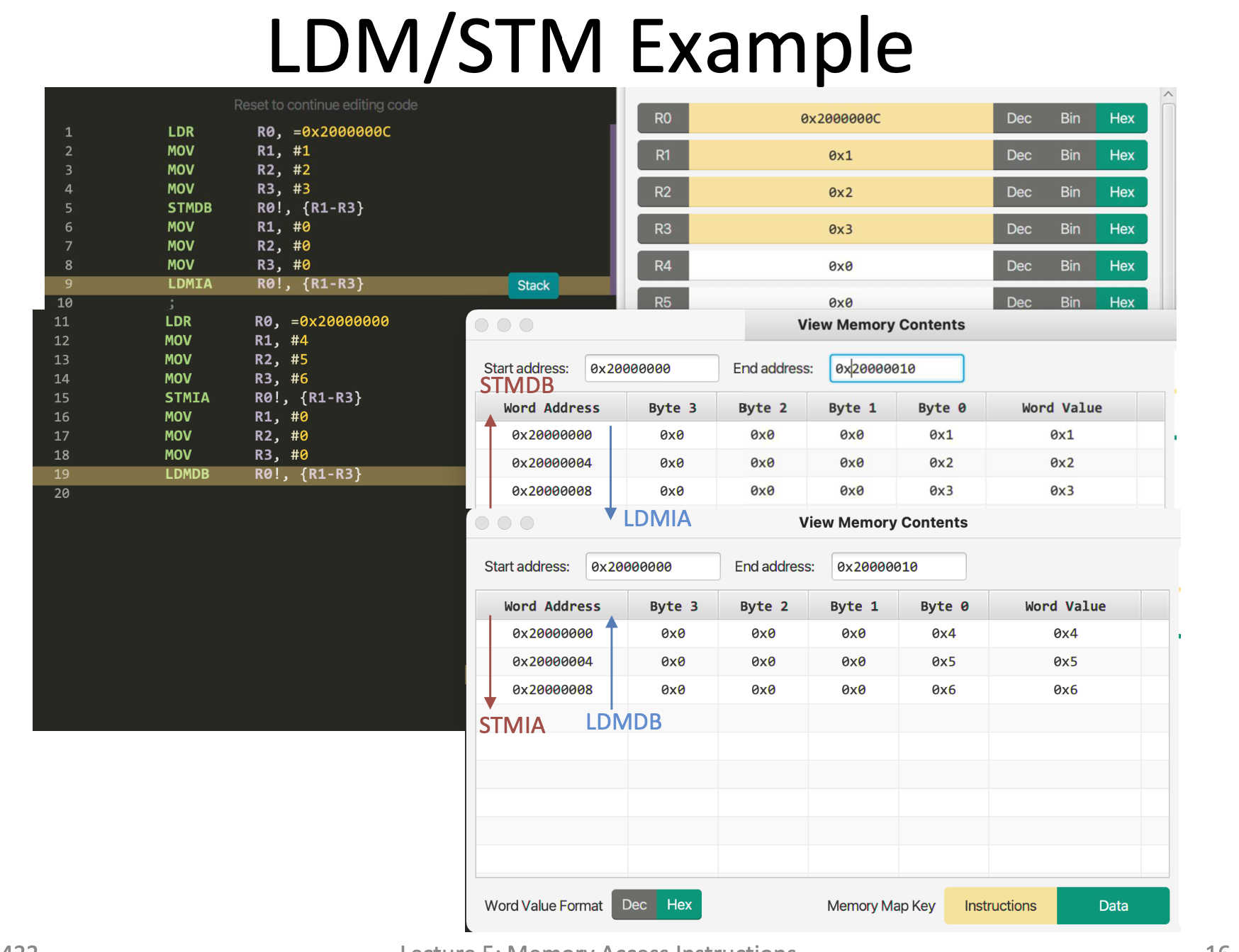
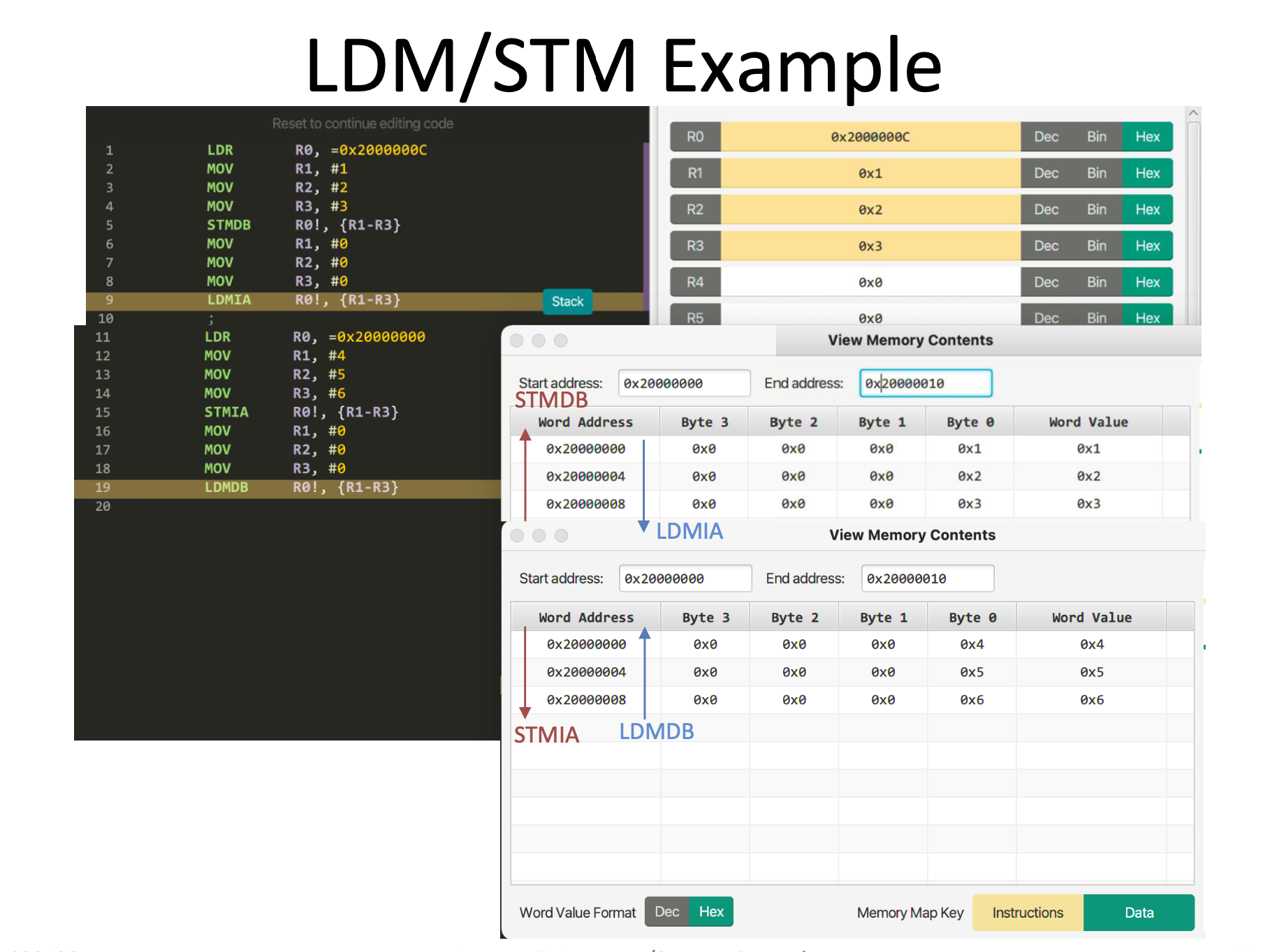
LDM/STM

Push and Pop
Subroutines
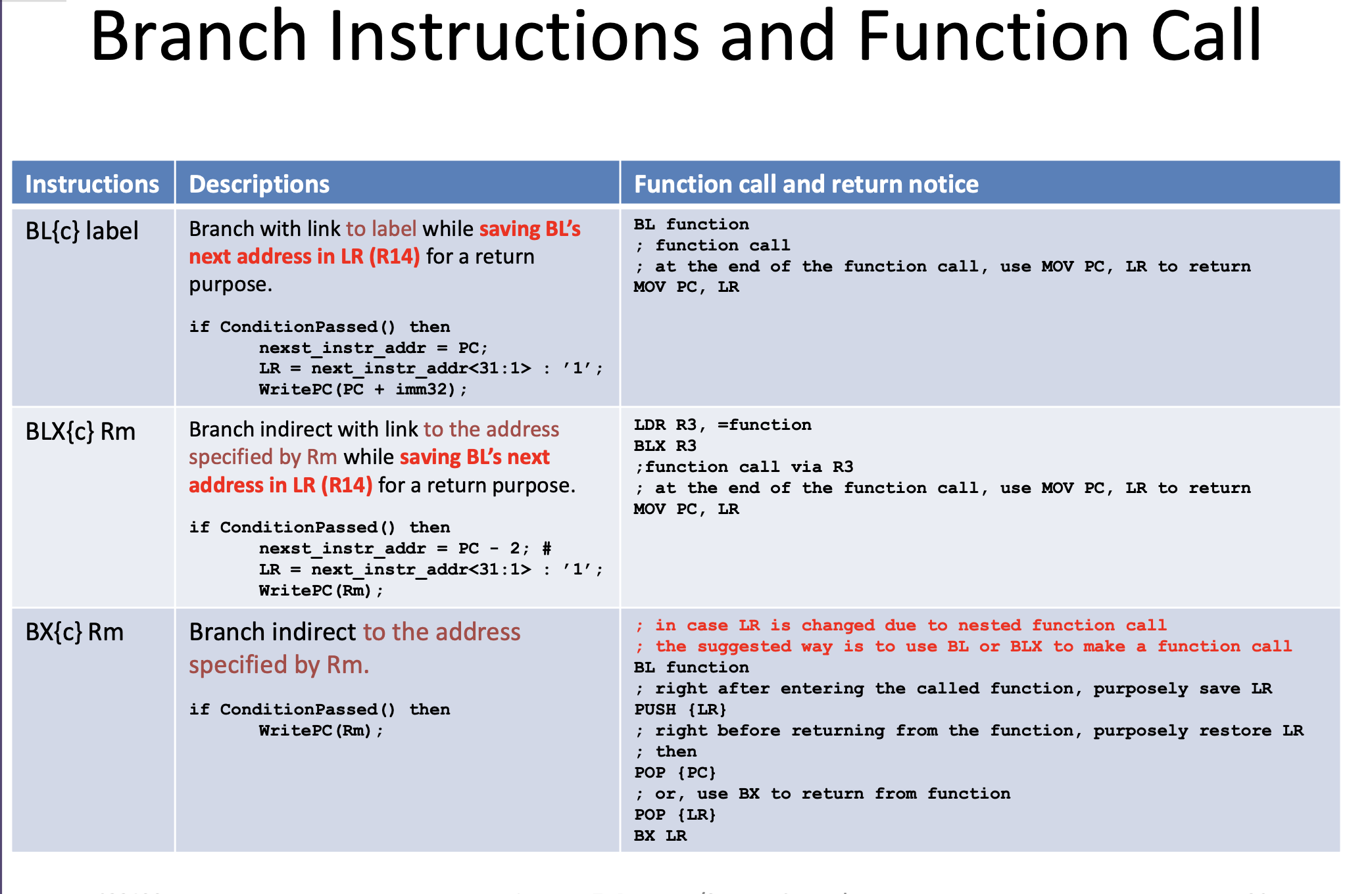
Branch Instructions
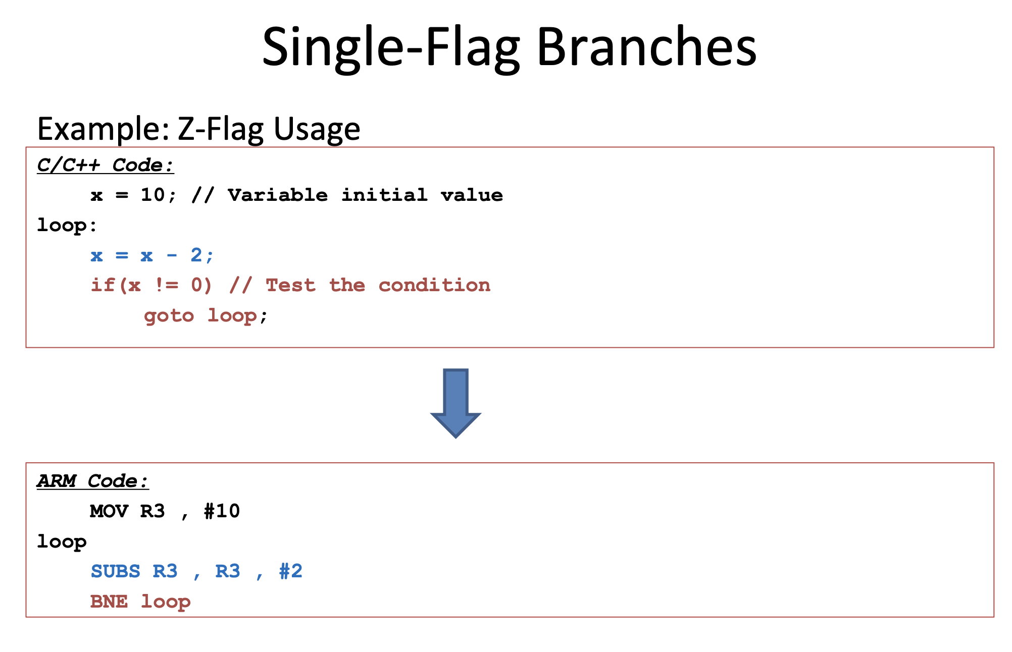
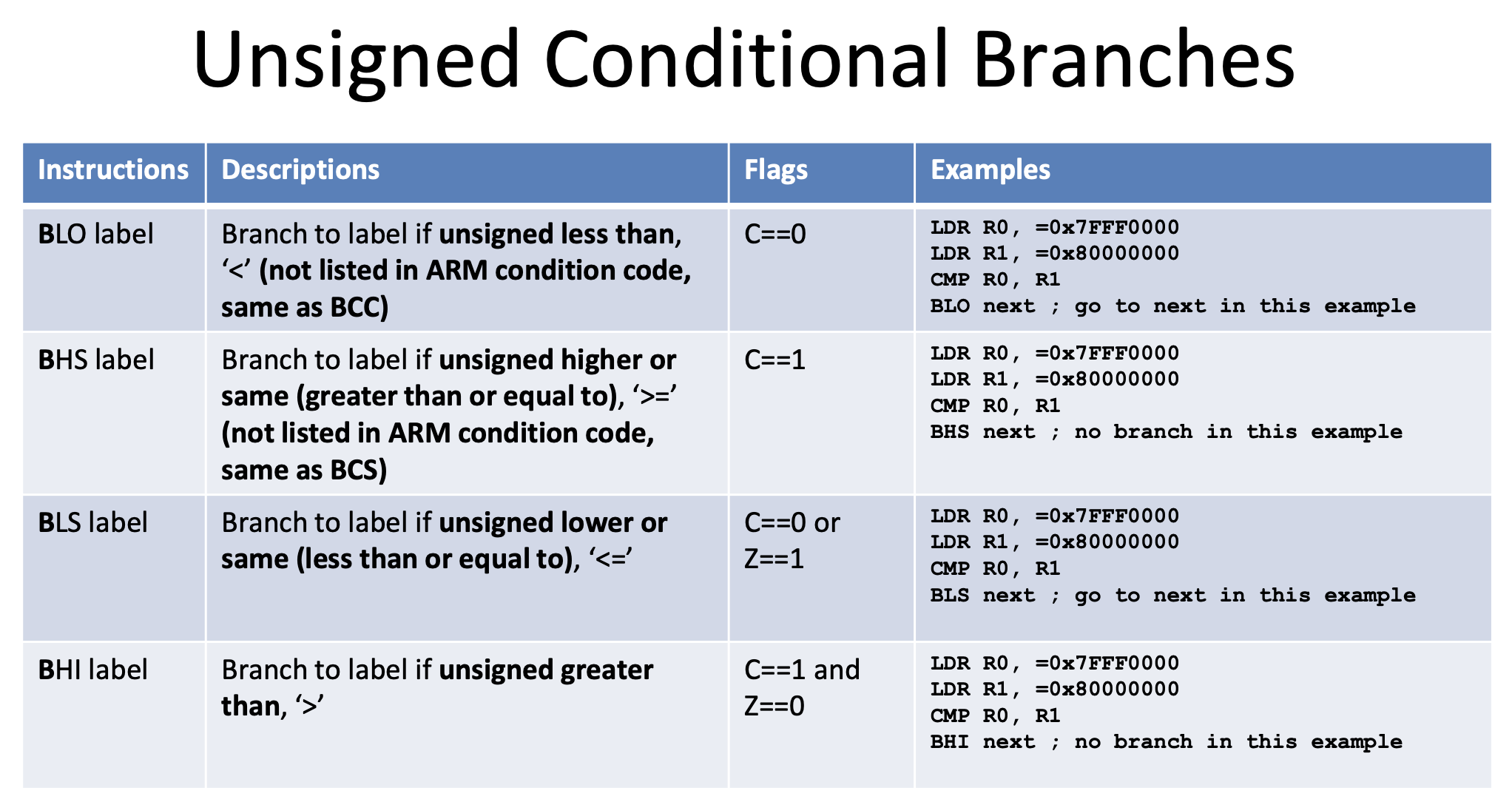
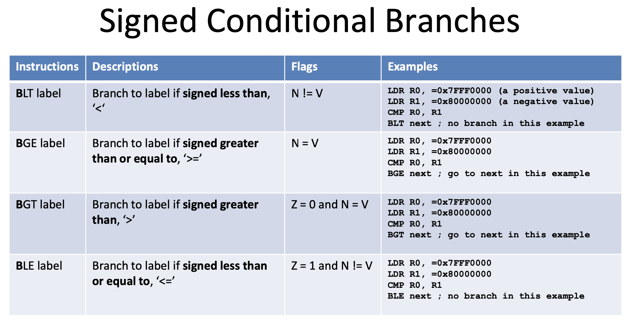
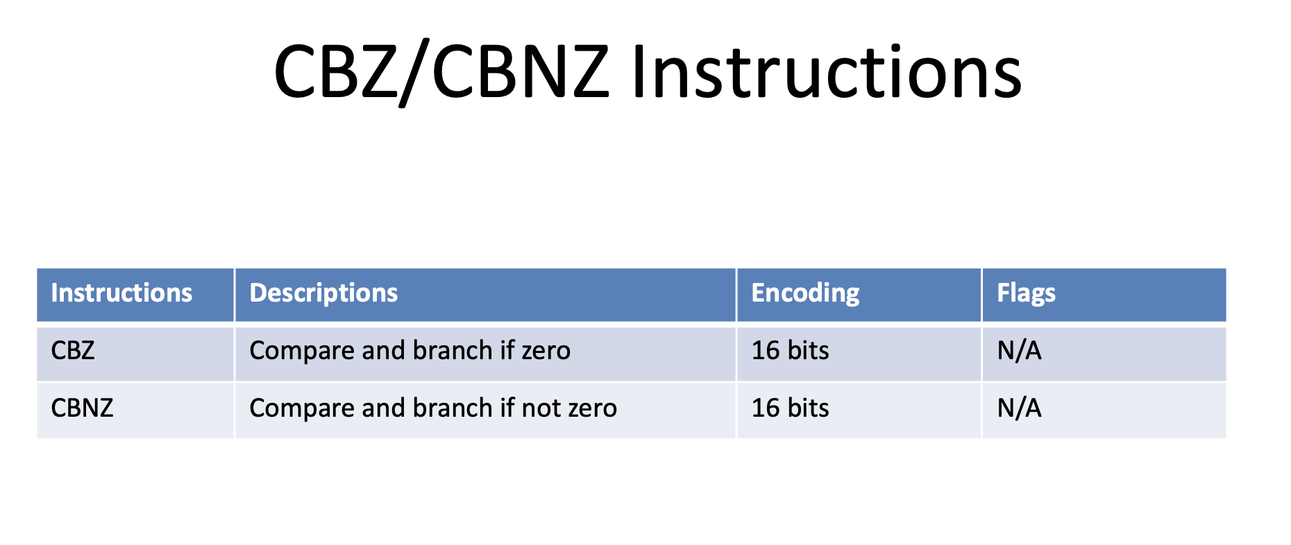
With Function Call
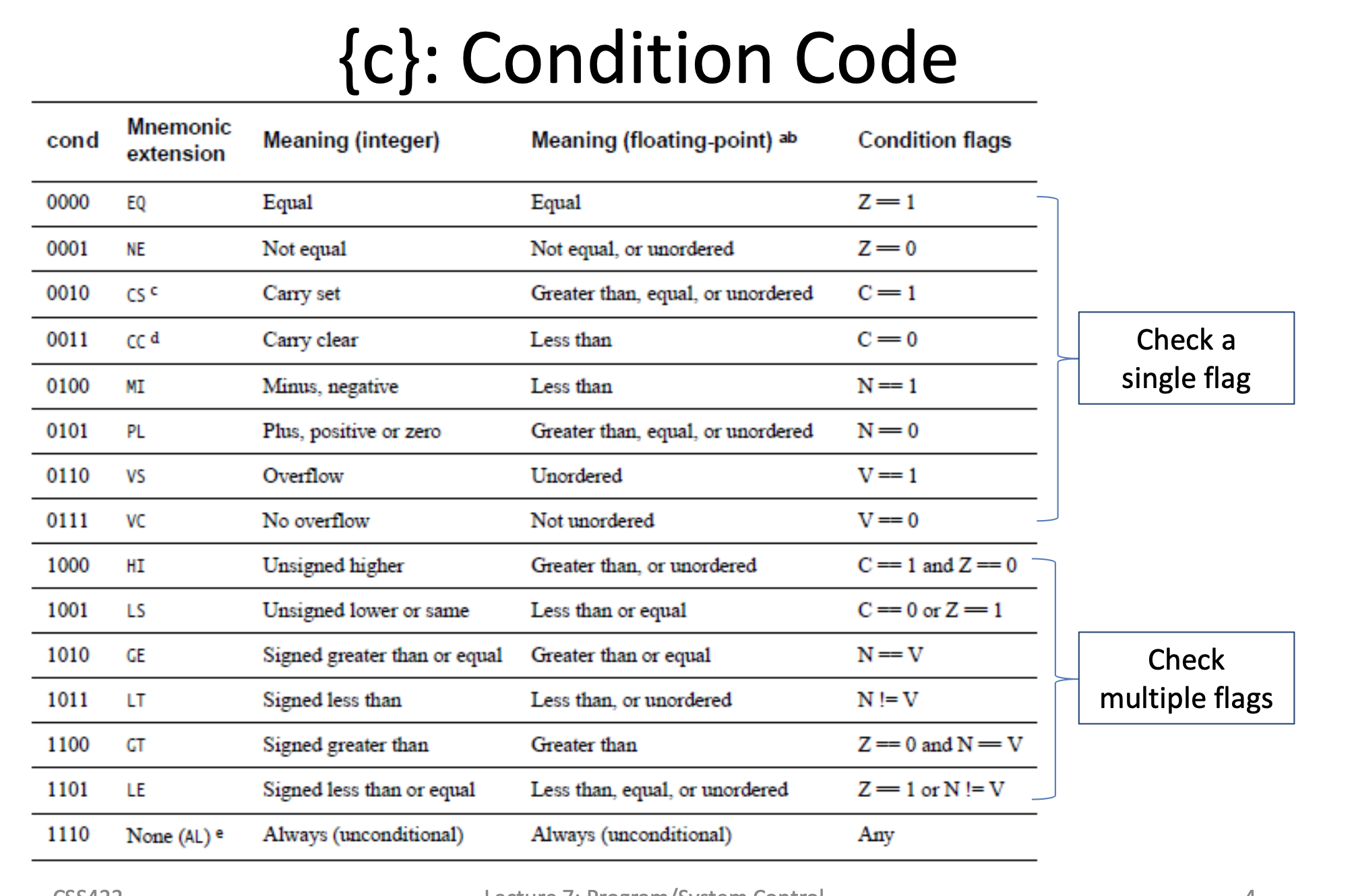
Condition Codes
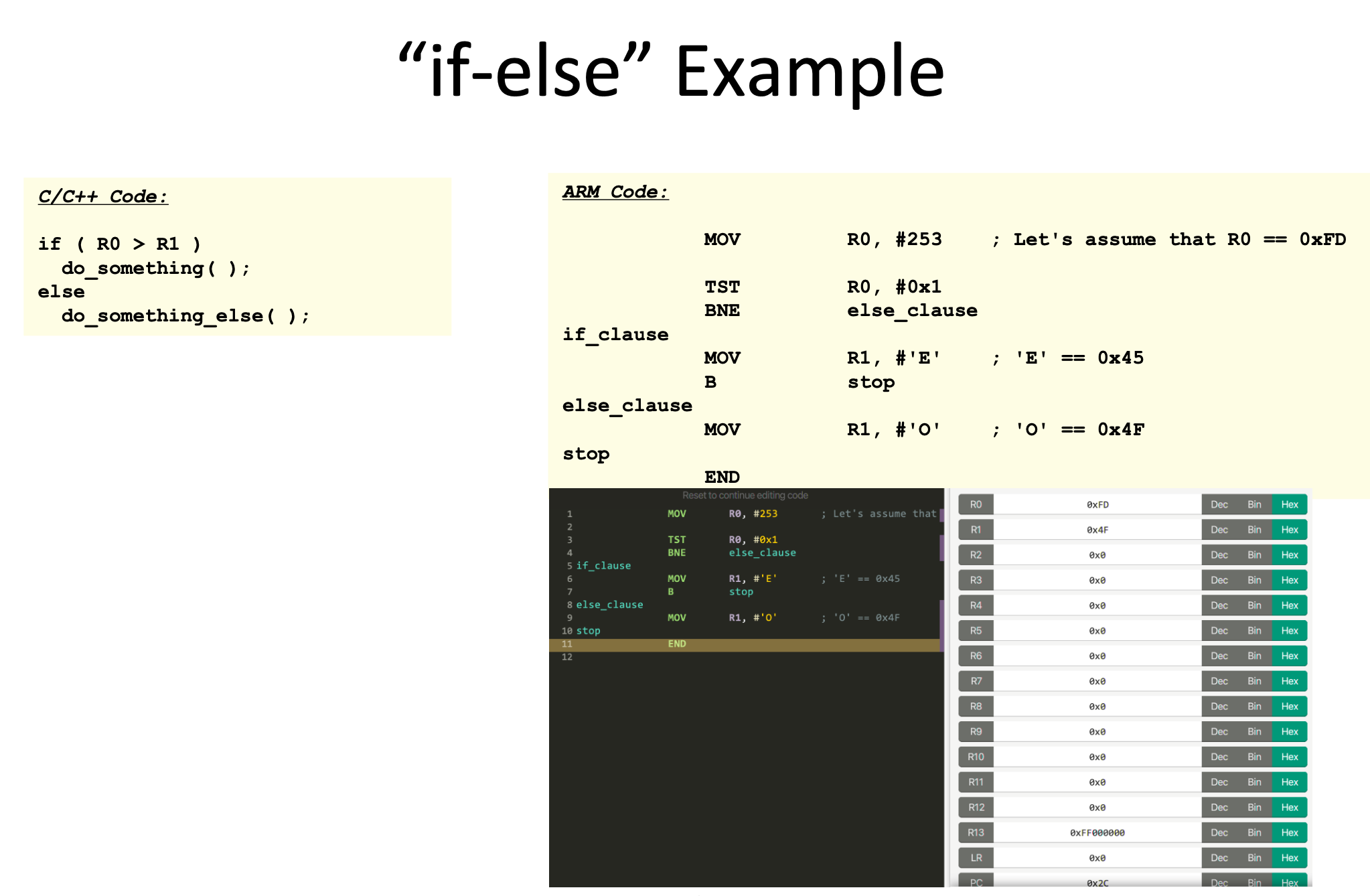
If/Else
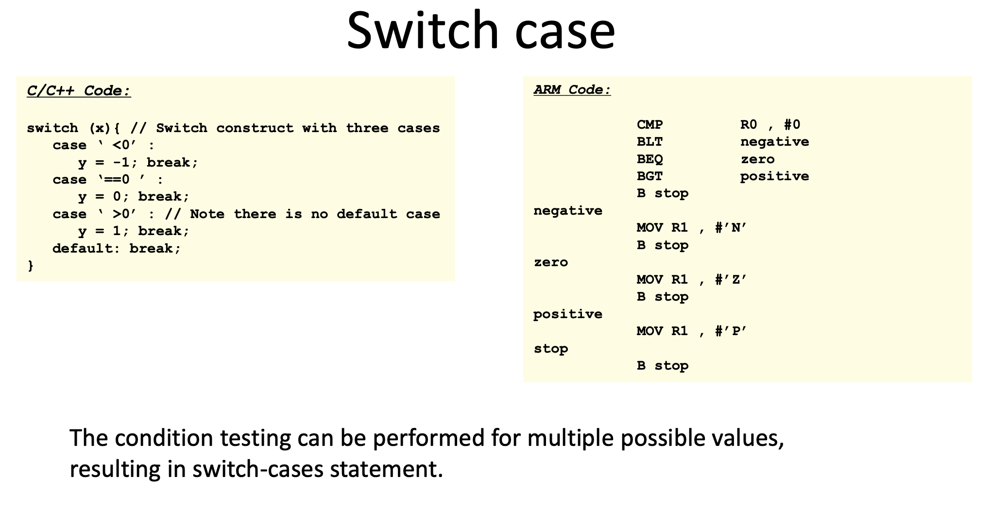
Switch Case
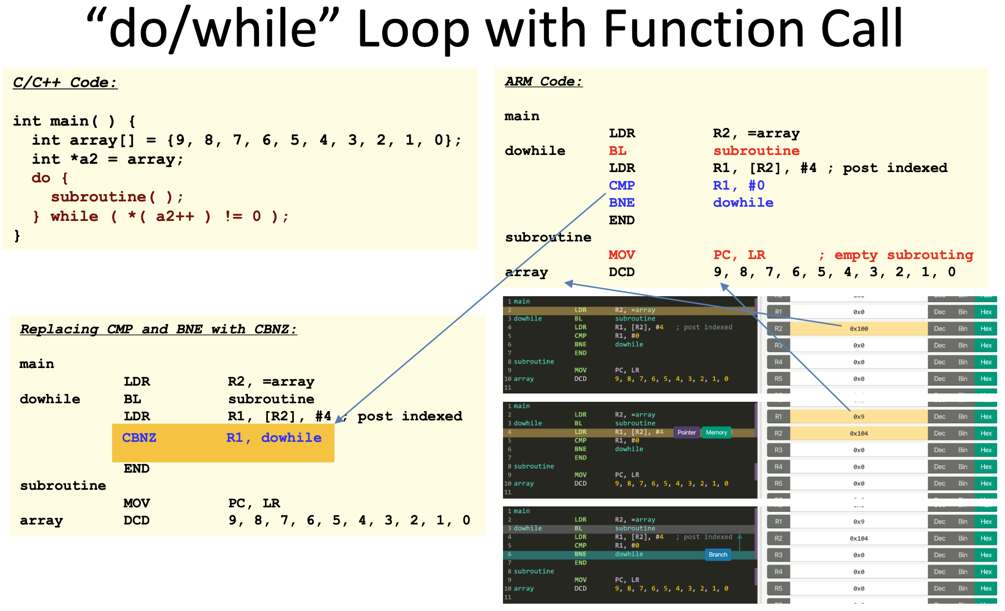
Do/While with function Call
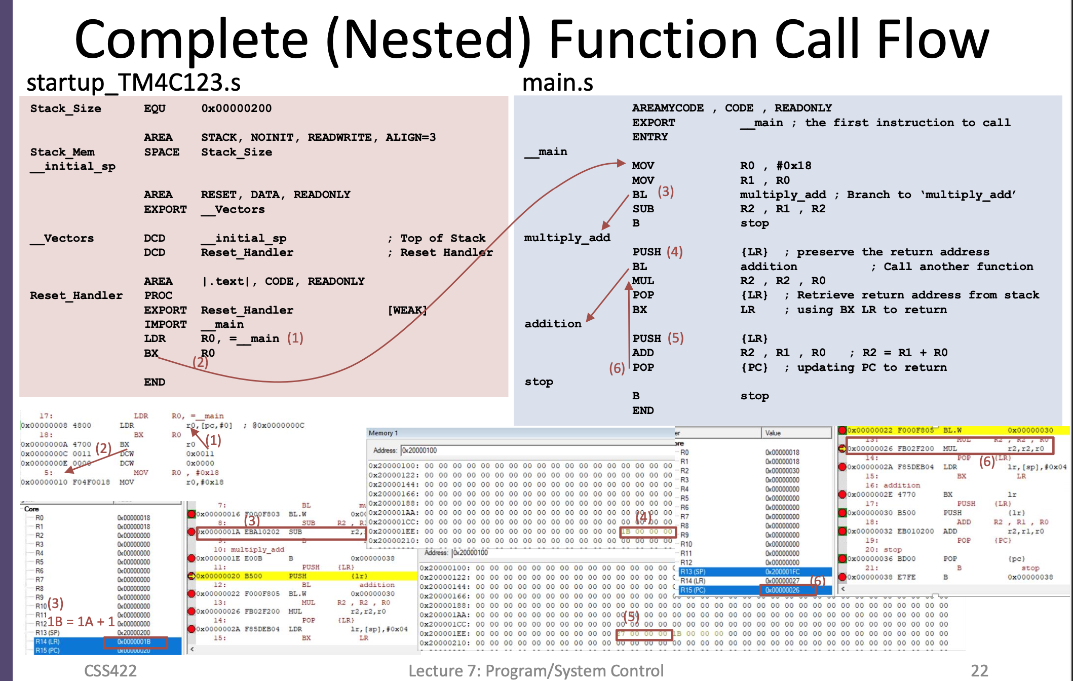
Nested Function Call
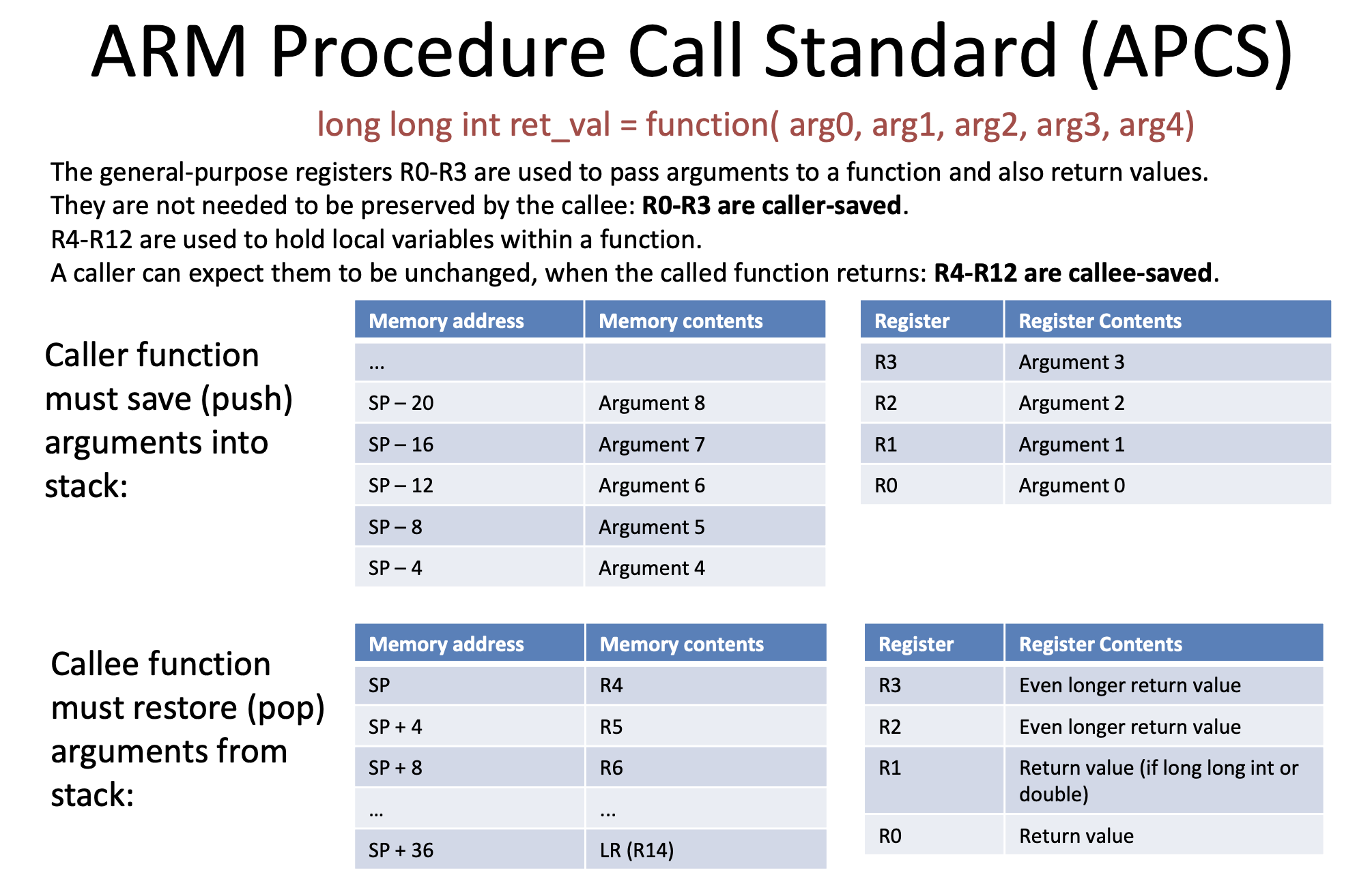
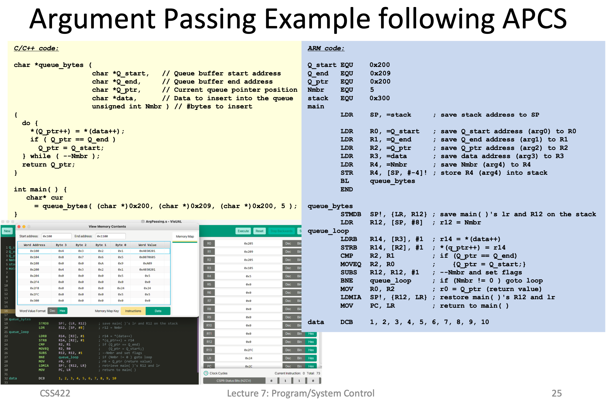
APSC (Arguements)
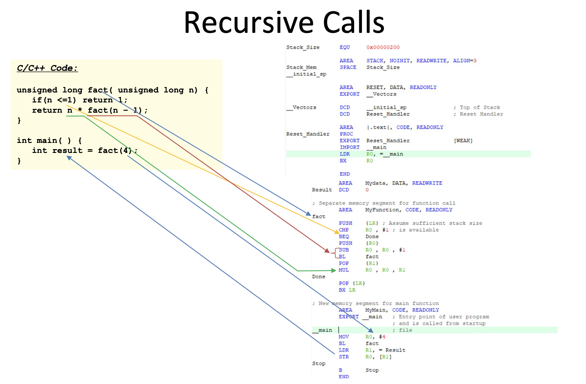
Recursive Calls
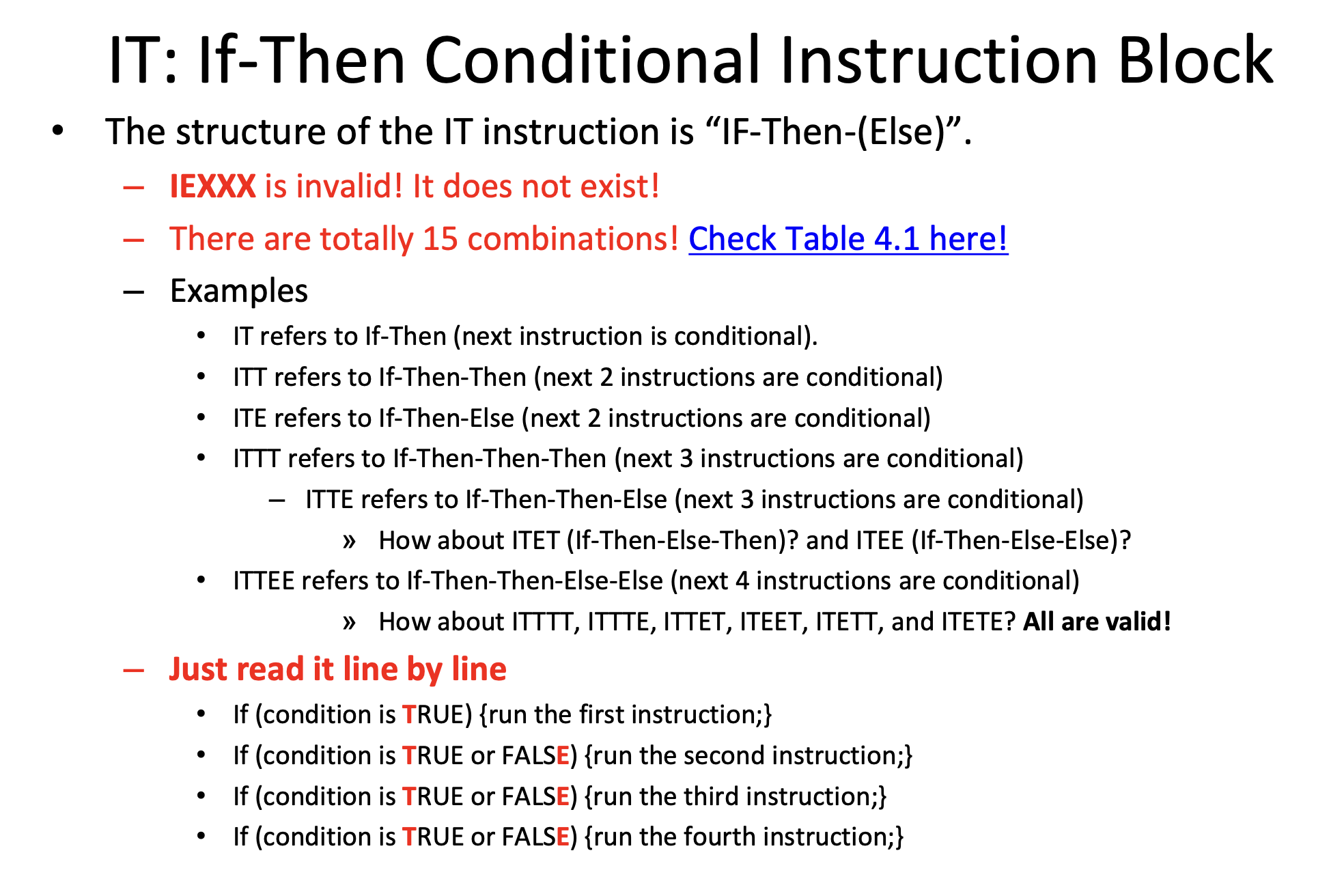
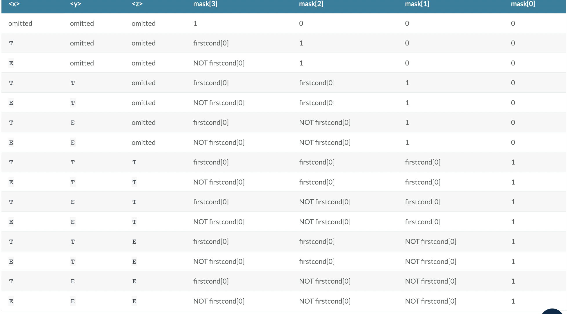
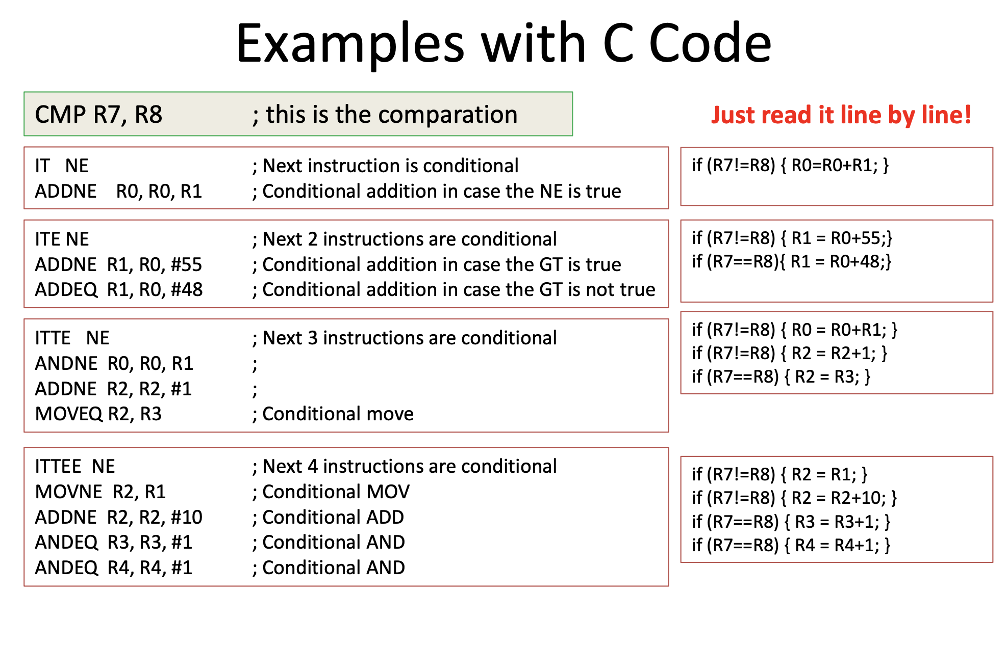
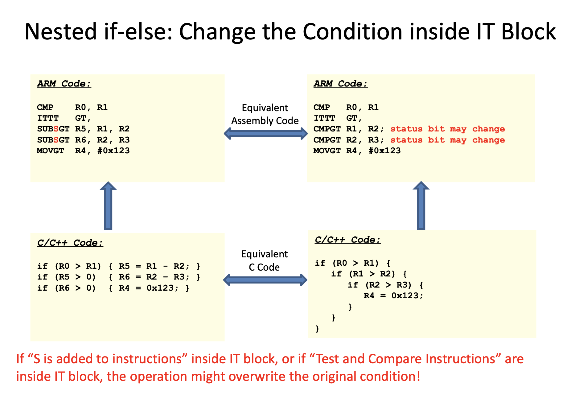
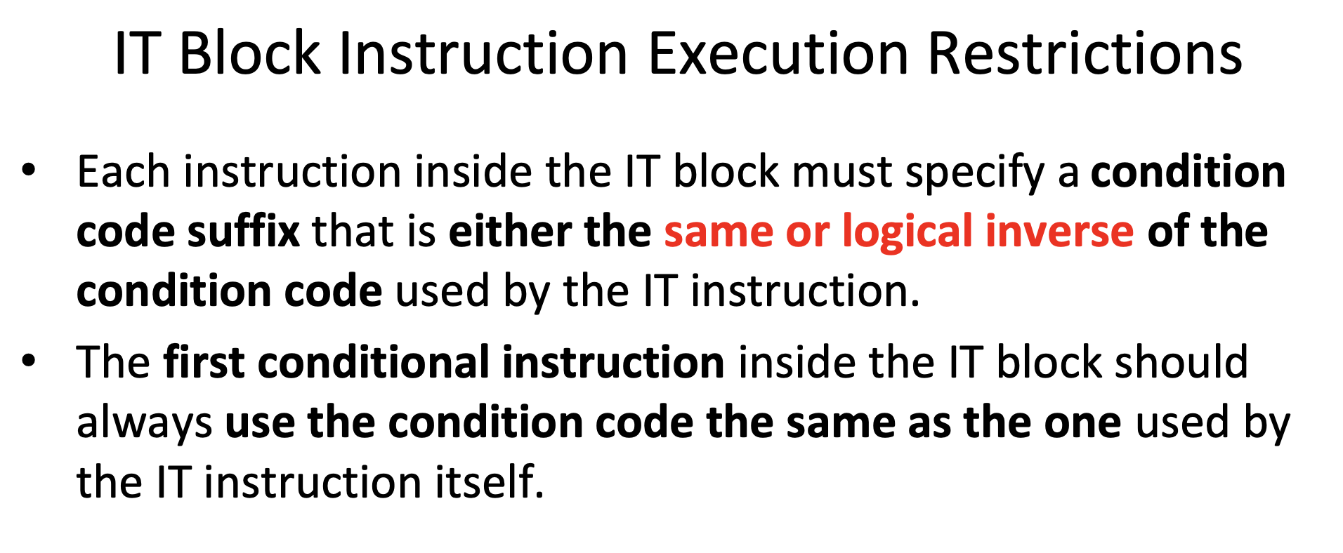
IT Block
Code Blocks
Multiply by 100
MOV R0, #13

LSL R1, R0, #6

LSL R3, R0, #5

LSL R4, R0, #2

ADD R2, R1,R3

ADD R2,R2,R4
Binary Search Tree
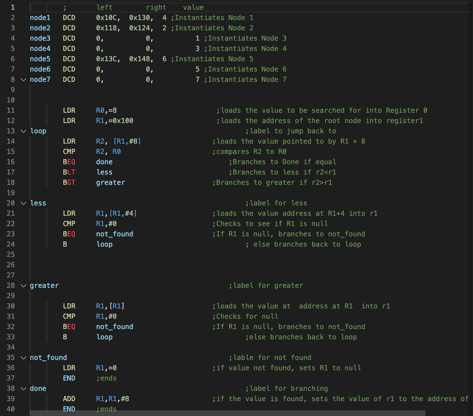
; left right value

node1 DCD 0x10C, 0x130, 4 ;Instantiates Node 1

node2 DCD 0x118, 0x124, 2 ;Instantiates Node 2

node3 DCD 0, 0, 1 ;Instantiates Node 3

node4 DCD 0, 0, 3 ;Instantiates Node 4

node5 DCD 0x13C, 0x148, 6 ;Instantiates Node 5

node6 DCD 0, 0, 5 ;Instantiates Node 6

node7 DCD 0, 0, 7 ;Instantiates Node 7

LDR R0,=8 ;loads the value to be searched for into Register 0

LDR R1,=0x100 ;loads the address of the root node into register1

loop ;label to jump back to

LDR R2, [R1,#8] ;loads the value pointed to by R1 + 8

CMP R2, R0 ;compares R2 to R0

BEQ done ;Branches to Done if equal

BLT less ;Branches to less if r2<r1

BGT greater ;Branches to greater if r2>r1

less ;label for less

LDR R1,[R1,#4] ;loads the value address at R1+4 into r1

CMP R1,#0 ;Checks to see if R1 is null

BEQ not_found ;If R1 is null, branches to not_found

B loop ; else branches back to loop

greater ;label for greater

LDR R1,[R1] ;loads the value at address at R1 into r1

CMP R1,#0 ;Checks for null

BEQ not_found ;If R1 is null, branches to not_found

B loop ;else branches back to loop

not_found ;lable for not found

LDR R1,=0 ;if value not found, sets R1 to null

END ;ends

done ;label for branching

ADD R1,R1,#8 ;if the value is found, sets the value of r1 to the address of the value

END ;ends
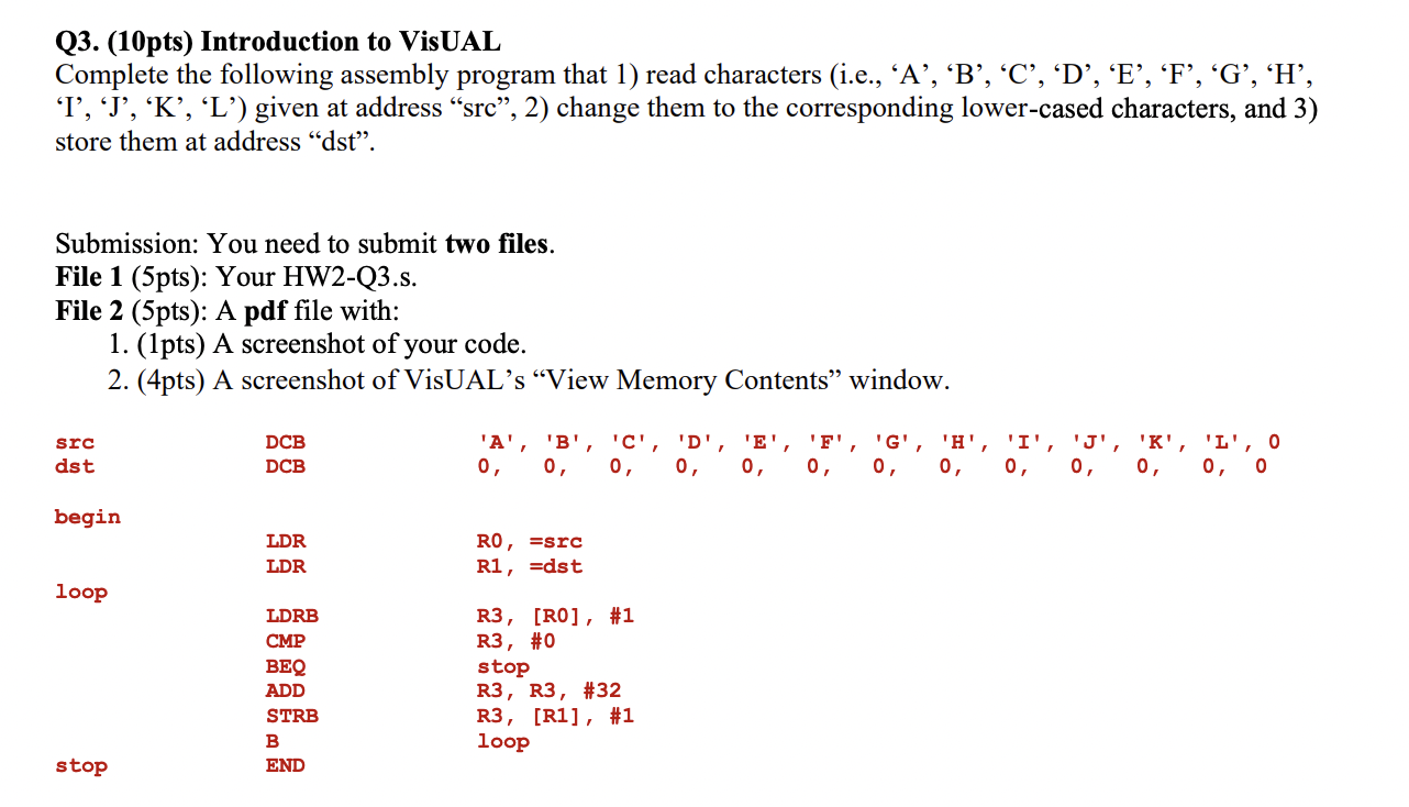
Capital to lowercase
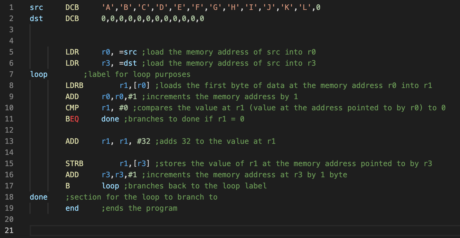
src DCB 'A','B','C','D','E','F','G','H','I','J','K','L',0

dst DCB 0,0,0,0,0,0,0,0,0,0,0,0

LDR r0, =src ;load the memory address of src into r0

LDR r3, =dst ;load the memory address of src into r3

loop ;label for loop purposes

LDRB r1,[r0] ;loads the first byte of data at the memory address r0 into r1

ADD r0,r0,#1 ;increments the memory address by 1

CMP r1, #0 ;compares the value at r1 (value at the address pointed to by r0) to 0

BEQ done ;branches to done if r1 = 0

ADD r1, r1, #32 ;adds 32 to the value at r1

STRB r1,[r3] ;stores the value of r1 at the memory address pointed to by r3

ADD r3,r3,#1 ;increments the memory address at r3 by 1 byte

B loop ;branches back to the loop label

done ;section for the loop to branch to

end ;ends the program
Quizzes/HW/Midterm Prep
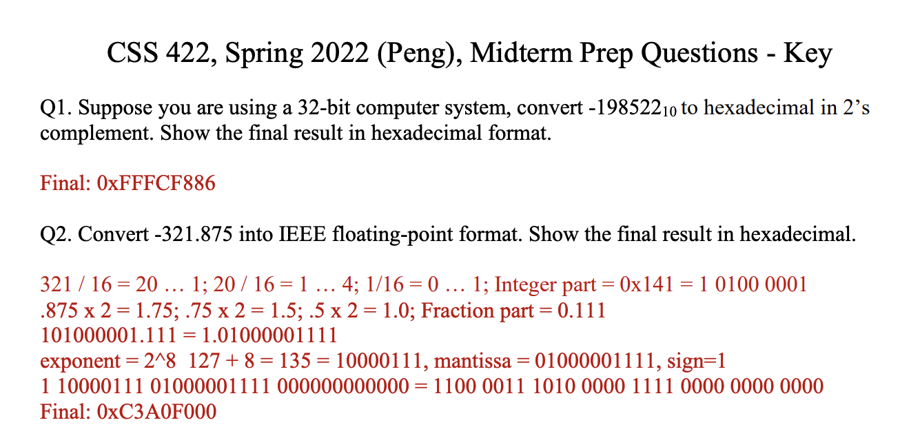
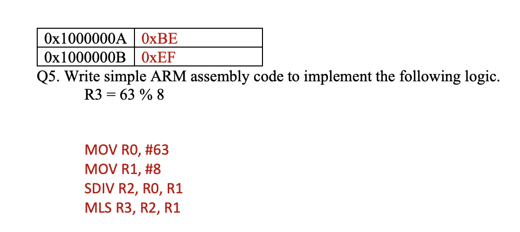
Midterm Prep
Quiz 1
Quiz 2
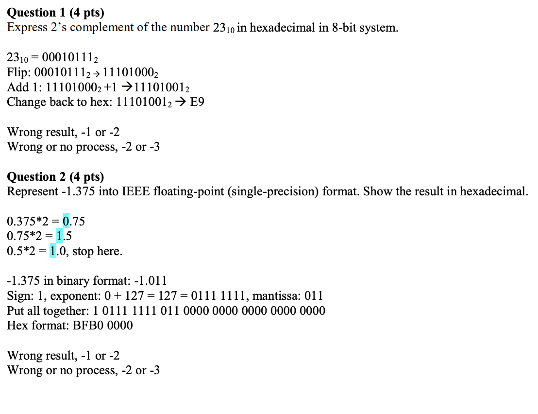
Quiz 3/6
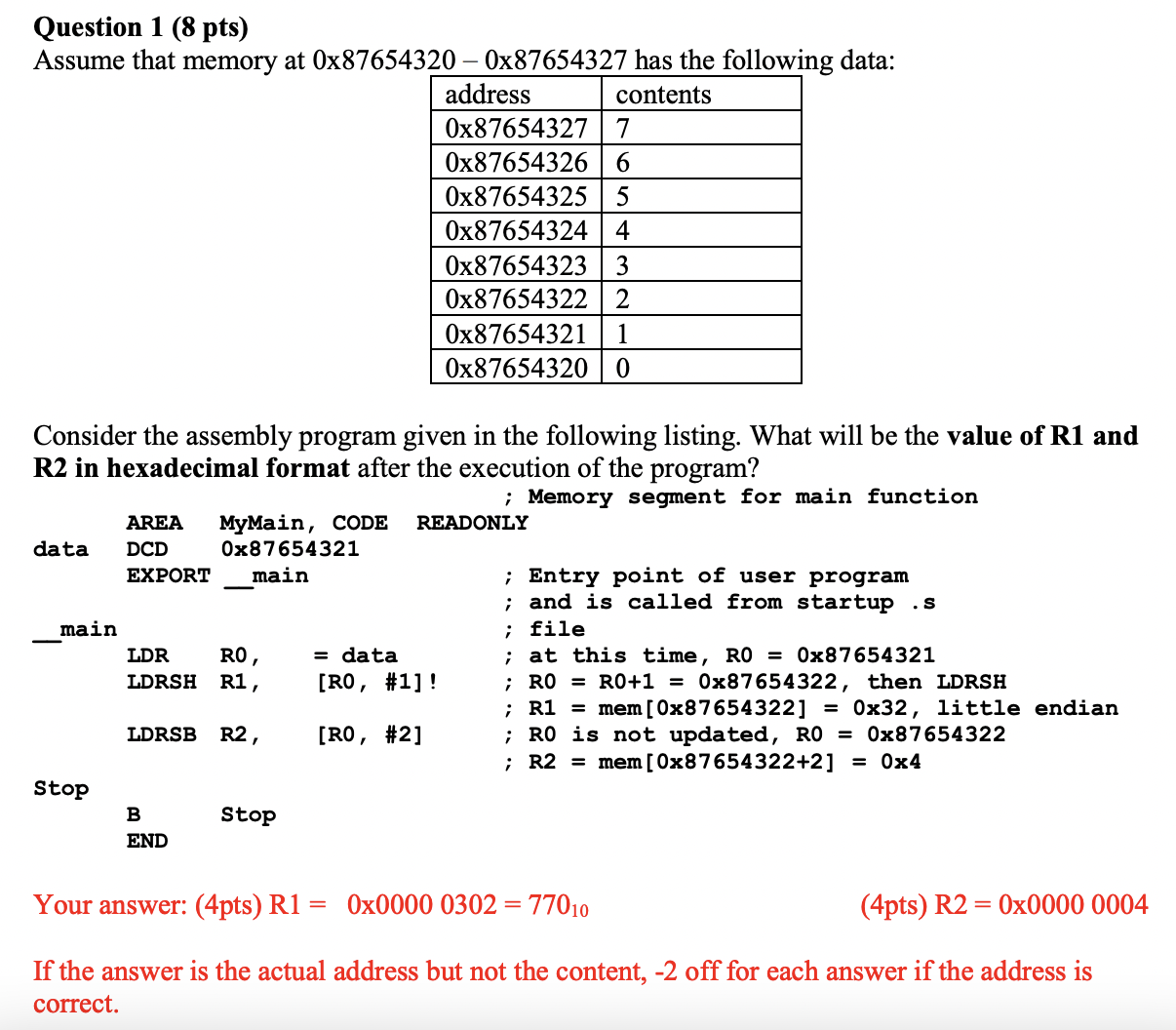
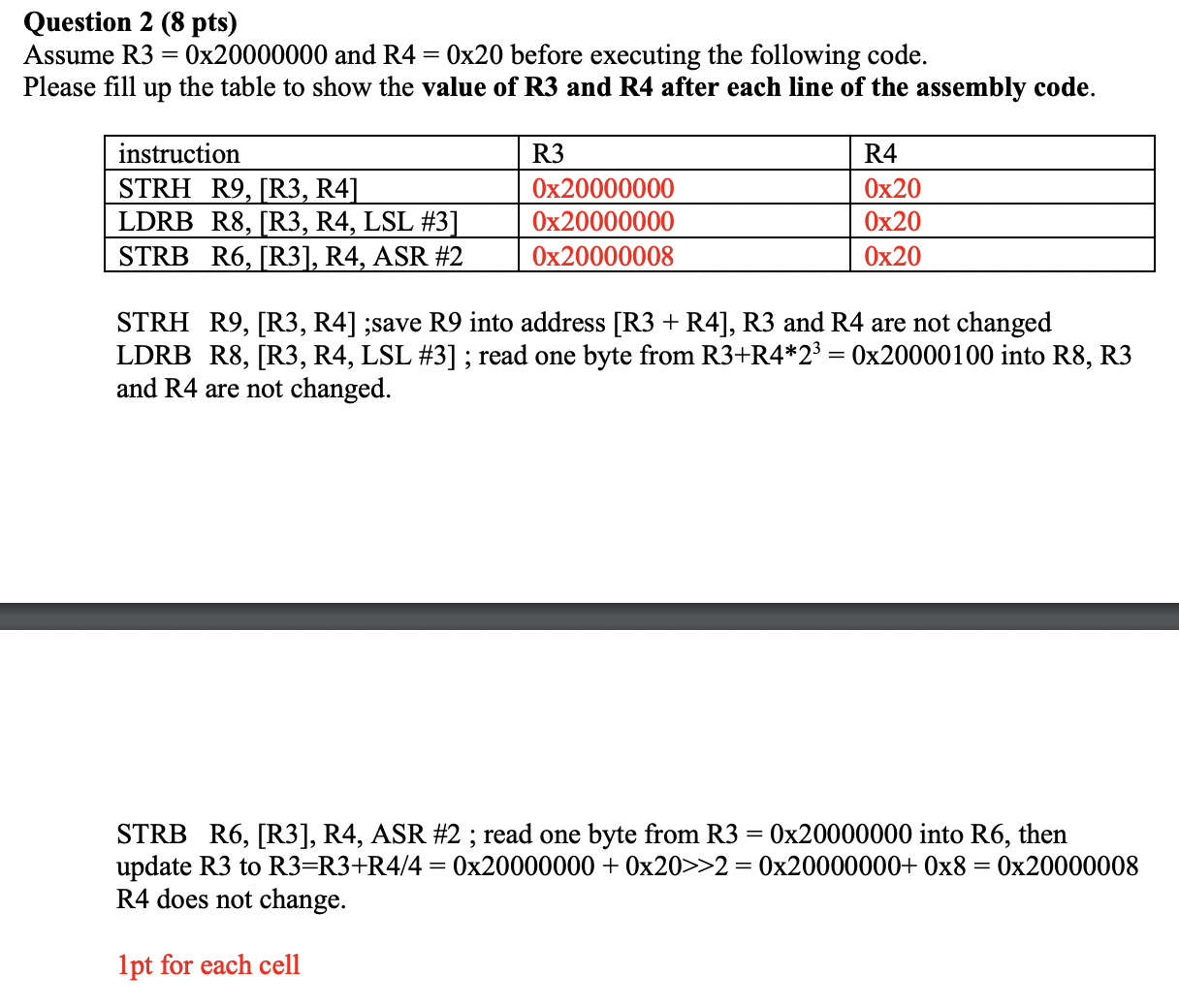
HW1
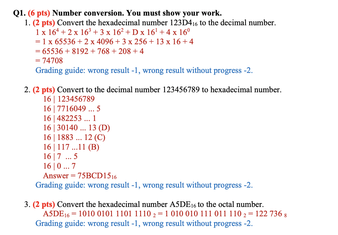
HW2

HW3
Quick Reference
