Operating Systems
CSS 430 - Operating Systems
Neso Operating Systems Video
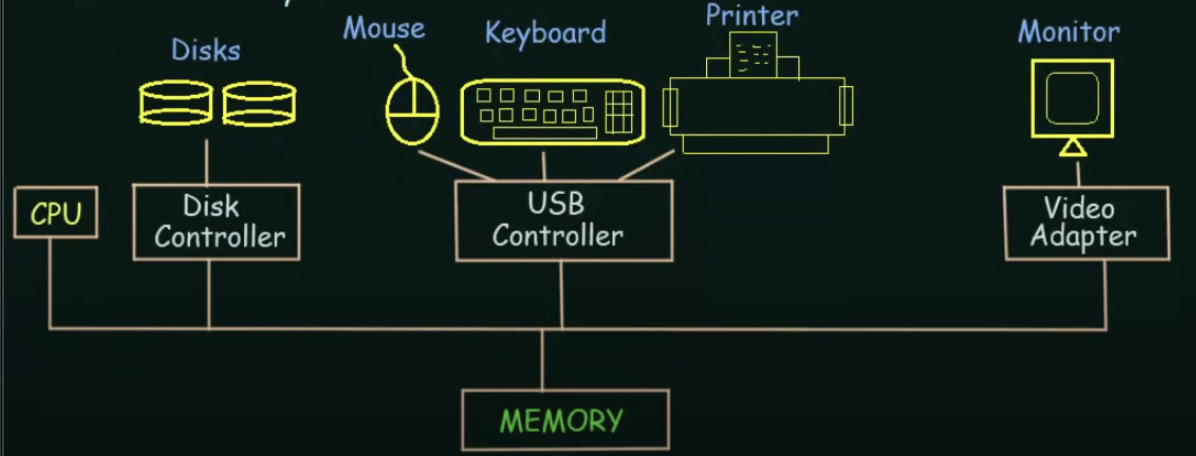
A modern general-purpose computer system consists of one or more CPUs and a number of device controllers connected through a common bus that provides access to shared memory
System Calls
System calls provide an interface to the services made available by an operating system
Two modes
- user mode
- privileged mode (kernel mode) Direct access to resources
When a user program makes a system call, for an instant, it's switched from user mode to kernel mode so it can use those resources (context switching)
The 6 types of System Calls Are:
- process control
- file management
- device management
- information maintenance
- communications
- protection
Interprocess Communication
Any process that shares data with another process is a cooperating process
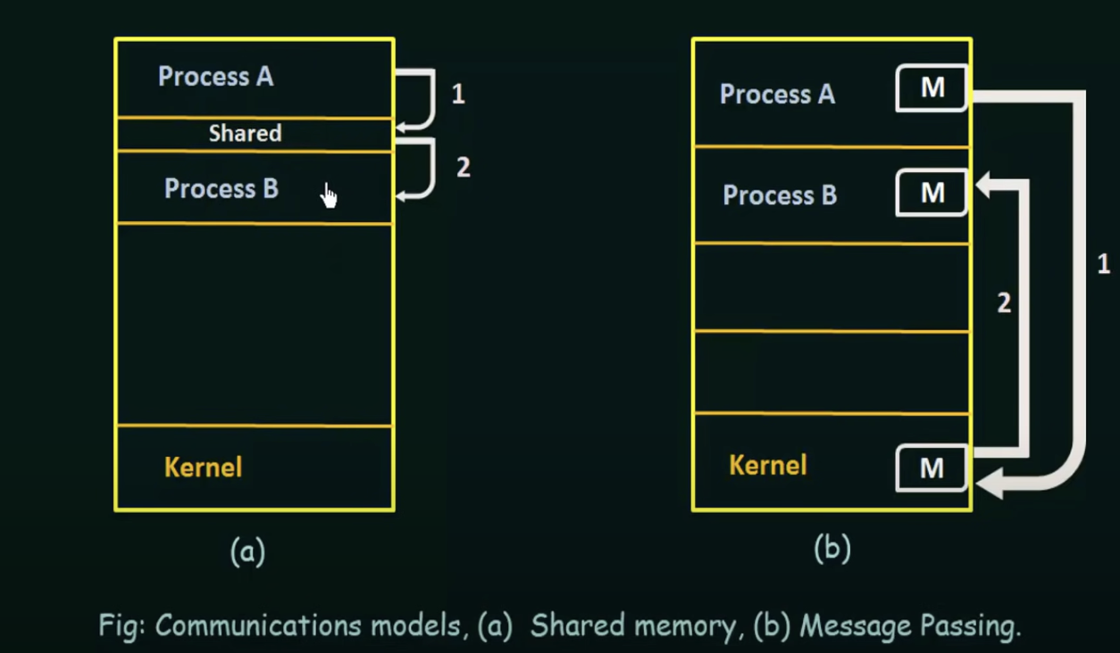
Shared Memory
In the shared memory model, a region of memory that is shared by cooperating processes is established
Processes can then exchange information by reading and writing data to the shared region
-
Typically, a shared memory region resides in the address space of the process creating the shared memory segment
-
Other processes that wish to communicate using this shared-memory segment must attach it to their address space
-
Normally, an operating system will try to prevent one processes from accessing another processes memory
-
Shared memory requires that two or more processes agree to remove any restriction on this
Producer Consumer Problem
A producer process produces information that is consumed by a consumer process
We need to make the producer and consumer so that the consumer doesn't try to consume what the producer has not consumed yet
-
To allow producer and consumer processes to run concurrently, we must have a buffer of items available that can be filled by the producer and emptied by the consumer.
-
The buffer will reside in a region of memory that is shared by the producer and consumer processes
-
A producer can produce one item while the consumer is consuming another item
-
The producer and consumer must be synchronized so that the consumer does not try to consume an item that has not been produced yet
Two Kinds of Buffers
- Bounded: Assumes a fixed buffer size. In this case, the consumer must wait if the buffer is empty, and the producer must wait if the buffer is full. Fixed buffer size
- Unbounded: No practical limit on the size of the buffer. The consumer may have to wait for new items, but the producer can always produce new items.
Message Passing
Communication takes place by means of messages exchanged by the cooperating processes
Message passing provides a mechanism to allow processes to communicate and synchronize their actions without sharing the same address space and is particularly useful in a distributed environment where the communicating processes may reside on different computers connected by a network
Provides at least 2 operations
- send(message)
- receive(message)
Messages sent can be either fixed or variable in size
- Fixed Size: The system level implementation is straightforward, however the task of programming is more difficult because you always have to keep the size of the message in mind
- Variable Size: Requires a more complex system level implementation, however programming becomes simpler
If processes P and Q want to communicate, they must send messages to and receive messages from each other.

A communication link bust exist between them
There are several methods for logically implementing a link, and the send()/receive() operations, like
- direct or indirect communication
- Synchronous or Asynchronous
- Automatic or explicit buffering
Direct or Indirect Communication
Processes can either use direct or indirect communication to communicate with each other
Direct Communication
each process must explicitly name sender or recepient
- send(p, message)
- receive(q, message)
A link is established between every pair of processes that want to communicate, the processes need to know only each other's identity to communicate.
A link is associated with exactly two processes
Between each pair there is exactly one link
A disadvantage of direct communication is the limited modularity of the resulting process definitions. Changing the identifier of a process may necessitate examining all other process definitions
Indirect communication
Messages are sent to and received from mailboxes or ports
- a mailbox can be viewed abstractly as an object into which messages can be placed by processes and from which messages can be removed
- each mailbox has a unique id
- two processes can communicate only if the processes have a shared mailbox
send(a, mailbox)
receive(a, mailbox)where a is the name of the mailbox
A communication link in this scheme has the following properties:
- a link is established between a pair of processes only if both members of the pair have a shared mailbox
- a link may be associated with more than two processes
- between each pair of communicating processes, there may be a number of different links, each with a corresponding mailbox
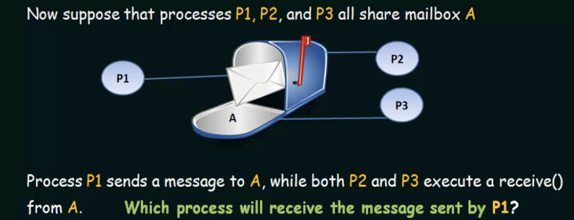
The answer depends on which of the following methods is chosen - allow a link to be associated with two processes at most (sender and receiver)
- allow at most one process at a time to execute a receive operation
- allow the system to select arbitrarily which process will receive the message. The system may also define an algorithm for selecting which process will receive the message (such as round robin). The system may identify the receiver to the sender.
A mailbox may be owned by either a process or the operating system., however, when the process terminates, the mailbox will disappear.
- message passing may be either blocking or non-blocking also known as synchronous and asynchronous
Blocking Send: the sending process is blocked until the message is received by the receiving process or by the mailbox.
Blocking Receive: the receiver blocks until a message is available
Nonblocking send: the sending process sends the message and then resumes operation
Non Blocking Receive: the receiver retrieves either a valid message or a NULL
Buffering
Whether communication is direct or indirect, messages exchanged by communicating processes reside in a temporary queue. Such queues can be implemented in three ways:
- Zero Capacity: The queue has a max length of 0, thus, the link cannot have any messages waiting in it. In this case, the sender must block until the recipient receives the message. You can only have one message going from sender to receiver
- Bounded Capacity: The queue has a finite length n, thus, at most n messages can reside in it. If a queue is not full when a new message is sent, the message is placed in the queue and the sender can continue execution without waiting. The links capacity is finite, however. If the link os full, the sender must block until space is available in the queue
- Unbounded capacity, the queue length is potentially infinite, thus the sender never blocks.
Sockets
A socket is an endpoint for communication
A pair of processes communicating over a network employ a pair of sockets - one for each process
A socket is identified by an IP address concatenated with a port number
The server waits for incoming client requests by listening to a specified port. Once a request is received, the server accepts a connection from the client socket to complete the connection
The packets traveling between hosts are delivered to the appropriate process based on the destination port number
Threads
A thread is a basic unit of execution
A thread is comprised of:
- a thread ID
- a program counter
- a register set
- a stack
It shares it's code, data, and file sections with its parent process and other threads belonging to that process
Multithreading Benefits
Responsiveness
Multithreading an interactive application may allow a program to continue running even if part of it is blocked or is performing a lengthy operation, thereby increasing responsiveness to the user
Resource Sharing
By default, threads share the memory and the resources of the process to which they belong. The benefit of sharing code and data is that it allows an application to have several different threads of activity within the same address space
Economy
Allocating memory and resources for process creation is costly. Because threads share the resources of the process to which they belong, it is more economical to create and context switch threads
Utilization of multiprocessor architecture
The benefits of multithreading can be greatly increased in a multiprocessor architecture where threads may be running in parallel on different processors. A single threaded process can only run on one CPU no matter how many are available. Multi-threading on a multi cpu machine increases concurrency
Multi threading models
In general, there are two types of threads:
- User threads: supported above the kernel and are managed without kernel support
- Kernel Threads: supported and managed directly by the operating system
For user threads to work with kernel threads, there must exist a relationship between them.
There are three common ways of establishing this relationship
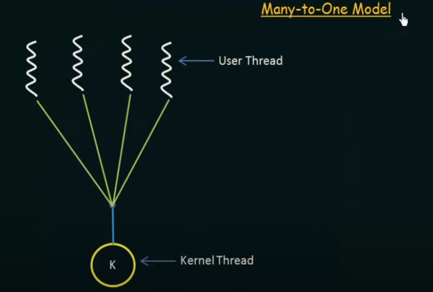
Many-to-one Model
Advantages
- maps many user-level threads to one kernel thread
- thread management is done by the thread library in user space
Disadvantages
- the entire process will block if a thread makes a blocking system call
- Because only one thread can access the kernel at a time, multiple threads are unable to run in parallel on multiprocessors
One-to-one Model
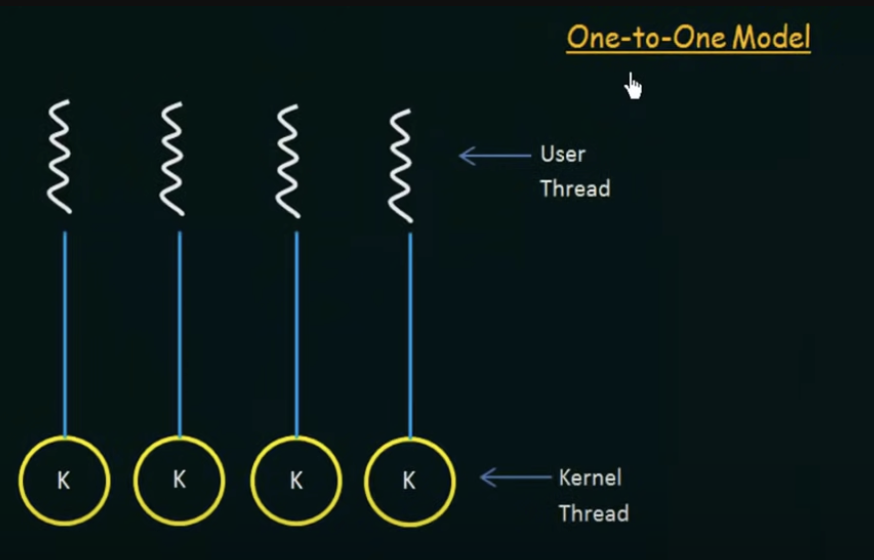
Advantages
- maps each user thread to a kernel thread.
- Provides more concurrency than the many-to-one model by allowing another thread to run when a thread makes a blocking system call
- also allows multiple threads to run in parallel on multiprocessors
Disadvantages
- Creating a user thread requires creating the corresponding kernel thread
- Because the overhead of creating kernel threads can burden performance, most implementations of this model restrict the number of threads supported by the system
Many-to-many model
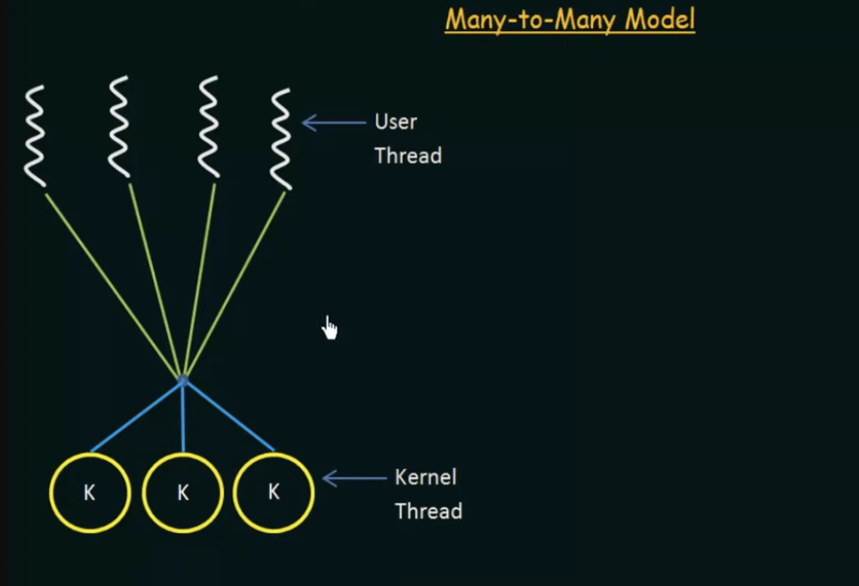
Implemented in most systems
Advantages
- multiplexes many user-level threads to a smaller or equal number of kernel threads
- the number of kernel threads may be specific to either a particular application or a particular machine
- Developers can create as many user threads as necessary and the corresponding kernel threads can run in parallel on a multiprocessor
- When a thread performs a blocking call, the kernel can schedule another thread for execution
Scheduling
In a single-processor system, only one process can run at a time. All others must wait until the cpu is free and can be rescheduled.
The objective of multiprogramming is to have some process running at all times to maximize utilization
A process is executed until it must wait, typically for the completion of some I/O request
Several processes are kept in memory at one time
When one process has to wait, the operating system takes the CPU away from that process and gives the CPU to another process and this pattern continues
CPU and I/O Burst Cycles
Process execution consists of a cycle of CPU execution and I/O wait. Processes alternate between these two states.
When a process has begun execution, it's under CPU state, otherwise it's waiting for an I/O event
CPU Burst: the time when a process is under CPU execution
I/O burst: when the process is waiting on an I/O event
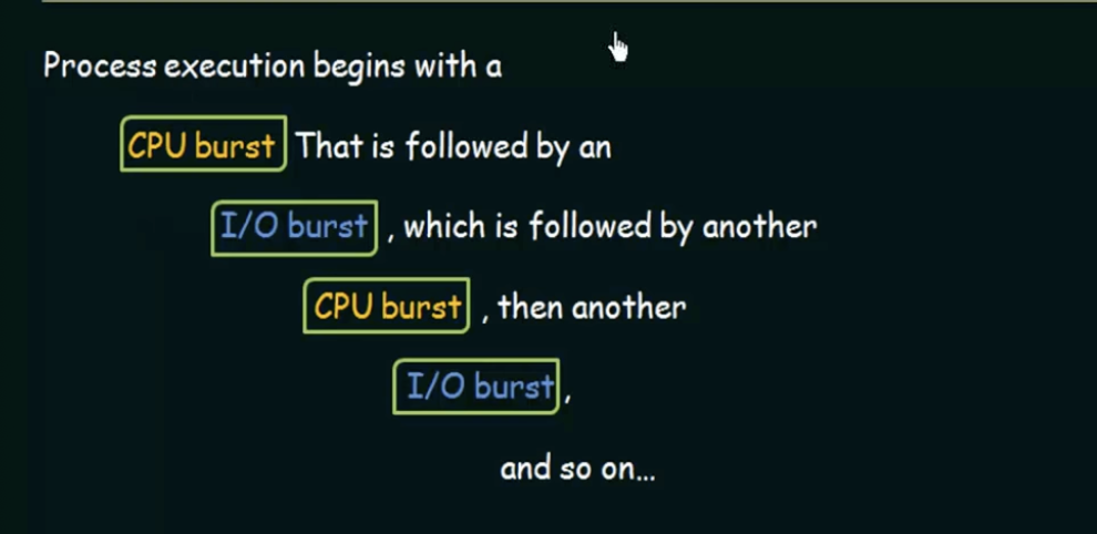
Eventually, the final CPU burst ends with a system request to terminate execution
Preemptive and NonPreemptive Scheduling
Whenever the CPU becomes idle, the operating system must select one of the processes in the ready queue to be executed. The selection process is carried out by the short-term scheduler(or CPU scheduler). The scheduler selects a process from the processes in memory that are ready to execute and allocates the CPU to that process
Dispatcher: The dispatcher is the module that gives control of the CPU to the process selected by the short-term scheduler. The time it takes for the dispatcher to stop one process and start another running is known as the dispatch latency
Preemptive Scheduling
CPU- Scheduling may take place under the following four circumstances
- When a process switches from running to waiting
- When a process switches from running to ready (for example, when an interrupt occurs)
- when a process switches from waiting to ready
- when a process terminates
For the first and last circumstance, there is no choice in terms of scheduling, we call this nonpreemptive, or, when a process is running, it will be allowed to use the CPU until its execution is complete
Scheduling Criteria
CPU Utilization
We want to keep the CPU as busy as possible. Conceptually, CPU utilization can range from 0 to 100 percent. In a real system, it should range from 40 percent to 90 percent
Throughput
The number of processes completed in a certain time unit. If the CPU is busy, the work is being done.
Turnaround Time
The time it takes from a process entering a ready queue to it's completion
Turn Around Time = Completion Time - Arrival Time
Waiting Time
The total sum of time a process spends waiting in the ready queue
Waiting time = Turn Around Time - Burst Time
Response time
The time it takes from submission until the first response is produced
FCFS (First Come First Serve)
- Simplist Algo
- The process that requests the CPU first is allocated the CPU first
- easily implemented with a FIFO queue
- Once a process is allocated to the CPU, it is removed from the head of the queue
- the average time is fairly long
- In many algorithms, the process with the smaller id breaks a tie
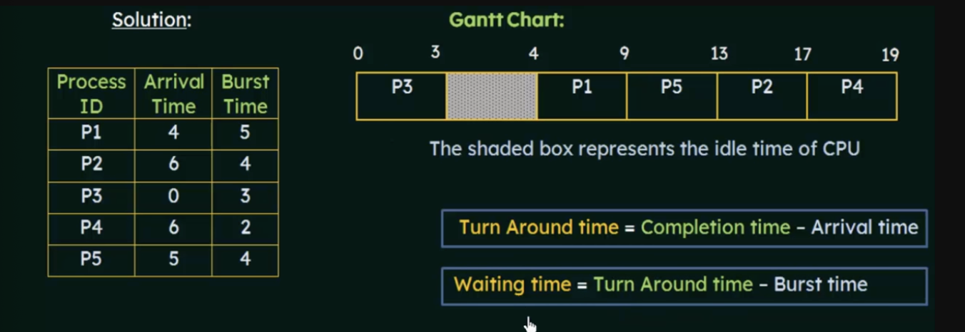
P5 Turnaround time = 8 (13-5)
P5 Waiting Time = 4(8-4)

(table is helpful)
SFJ
- When the CPU is available, it is assigned to the process that has the next smallest remaining CPU burst
- if the next CPU bursts are the same, FCFS scheduling is used to break tie
- Can be preemptive or non preemptive
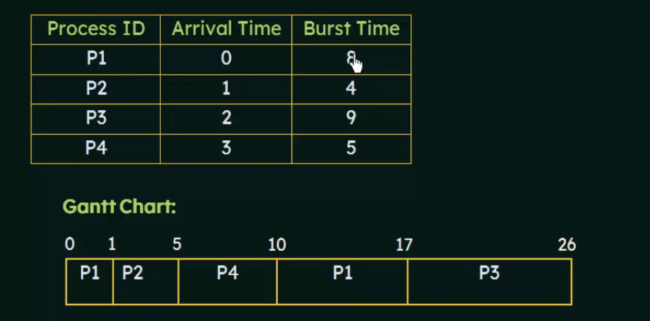
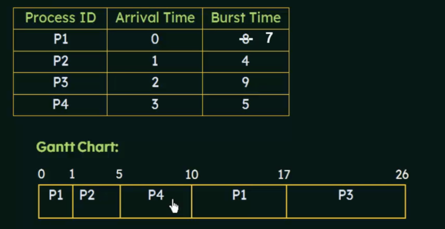
Waiting time = Total Waiting Time - No. of milliseconds Process Executed previously - arrival time
Preemptive SJF
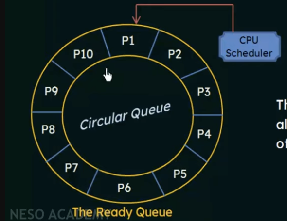
- the ready queue is a FIFO queue of processes
- new processes are added to the tail of the queue
- the cpu scheduler picks the first process from the ready queue, sets a timer to interrupt after 1 time quantum, and dispatches the process
- once the timer interrupts again, the scheduler will remove the process if it hasn't completed, move it to the back of the queue, and continue on
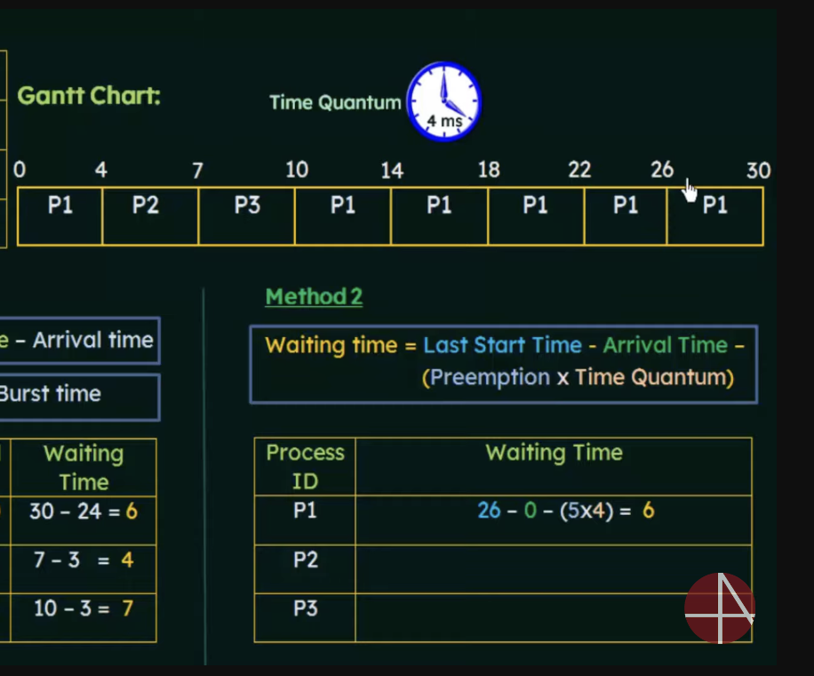
Turnaround time and waiting time for Round Robin


One method for calculating
Turn around time = completion time - arrival time
waiting time = Turnaround time - burst time
Or we can use
Waiting time = final start time - arrival time - (preemption x time quantum) where preemption = num times the process was preempted
P1 was preempted
Multilevel Queue
A class of scheduling algorithms has been created for situations in which processes are easily classified into different groups
Example: Foreground processes and Background processes.
- these have different response time requirements and different scheduling needs
- Additionally, foreground processes may have priority over background processes
The Multilevel queue partitions the ready queue into several separate queues
Each queue may have a different scheduling algorithm such as Round Robin for foreground and First come First serve for background
Multilevel Feedback queue
In multilevel feedback queue, processes may move from one queue to another. You separate them according to the characteristics of their CPU bursts. If a process uses too much CPU time, it will be moved to a lower priority queue
This leaves the I/O bound and interactive processes in the higher-priority queues
- a process that waits too long in a lower priority queue may be moved to a higher priority queue
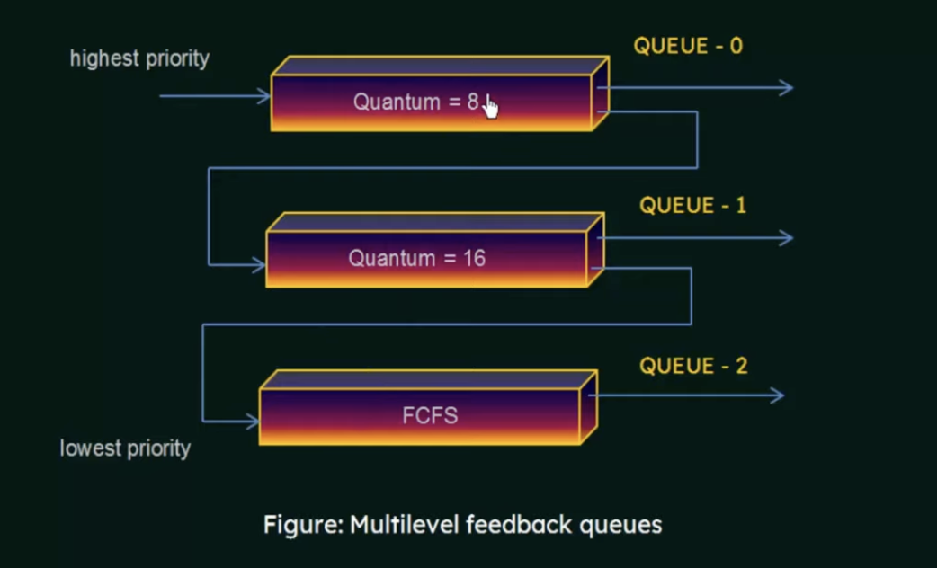
In general, A MFQ is defined by:
- number of queues
- the scheduling algorithm for each queue
- the method use to determine when to upgrade a process to a higher priority queue
- the method used to determine when to demote a process to a lower priority queue
- the method used to determine which queue a process will enter when that process needs service
Process Synchronization
A cooperating process is one that can affect or be affected by other processes executing in the system
Cooperating processes can either
- directly share a logical address space (that is, both code and data)
- or be allowed to share data only through files or messages
This leads to a problem where concurrent access to shared data may result in data inconsistency
Shared memory systems is a good example of the shared data problem
To understand this, we need to have an understanding of how this happens at the machine level (assembly)
When several processes access and manipulate the same data concurrently and the outcome of the execution depends on the particular order in which the access takes place, it is called a race condition
Since we don't want race conditions, we need process synchronization.
To deal with this we can use a few methods
Critical Section Problem
Consider a system with n processes (N1, N2....Nn)
Each process has a segment of code called a critical section in which the process may be changing common variables, updating a table, writing a file, and so on
When one process is executing in its critical section, no other process is allowed to execute in its critical section.
That is, no two processes are executing in their critical sections at the same time
The critical-section problem is to design a protocol that the processes can use to cooperate
- Each process must request permission to enter its critical section
- the section of code implementing this request is the entry section
- the critical section may be followed by an exit section
- the remaining code is the remainder section
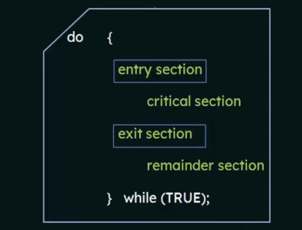
A solution to the critical-section problem must satisfy the following three requirements
Requirements
- Mutual Exclusion: If a process P is executing in its critical section, then no other processes can be executing in their critical sections.
- Progress: If no process is executing in its critical section and some processes wish to enter their critical sections, then only those processes that are not executing in their remainder sections can participate in the decision on which will enter its critical section next, and this selection cannot be postponed indefinitely.
- Bounded Waiting: There exists a bound, or limit on the number of times that other processes are allowed to enter their critical sections after a process has made a request to enter its critical section and before that request is accepted (otherwise it may lead to starvation)
Peterson's Solution
Petersons solution is a 'humble' algorithm
- a classic software-based solution to the critical section problem
- may not work correctly on modern architectures
- provides good description of solving the critical-section problem
The solution is restricted to two processes that alternate execution between their critical sections and remainder sections, we will call them
Peterson's solution also requires two data items to be shared between the two processes:
int turn: indicate whose turn it is to enter its critical section, this is a shared variableboolean flag[2]:used to indicate if a process is ready to enter its critical section
When a process is ready to enter its critical section, it will set its flag to true.
When process
When one process wants to enter its critical section, it offers its turn to the other process
Structure of
do {
 flag[i] = true;
 turn = j;
 while(flag[j] && turn ==[j]); // this semicolon keeps this secion looping while it's true, so only when it's false does it move to the critical section
	 //critical section
flag[i] = false;
	//remainder section
}while(TRUE);
Structure of
do {
 flag[j] = true;
 turn = i;
 while(flag[i] && turn ==[i]); // this semicolon keeps this secion looping while it's true, so only when it's false does it move to the critical section
	 //critical section
flag[i] = false;
	//remainder section
}while(TRUE);
Test and Set Lock
- a hardware solution to the synchronization problem
- there is a shared lock variable which can take either of the two values, 0 or 1 (0 = unlocked, 1 = locked)
- before entering into a critical section, a process inquires about the lock
- If it is locked, it keeps waiting until it becomes free
- if it is not locked, it takes the lock and executes the critical section
Test and Set definition
boolean TestAndSet(boolean *target){
boolean rv= *target;
*target = TRUE;
return rv;
}
This is an atomic operation
Example
lock is always 0 initially, and we are passing lock by reference
process p1
do{
while(TestAndSet(&lock));//if the while condition is false, it will continue processing, however, we set the lock value to true so other processes cannot take the lock
//do nothing
//critical section
lock = FALSE;
//remainder section
} while(TRUE)
Advantages
- Satisfies mutual-exclusion
Disadvantages
- It does not satisfy bounded waiting
Semaphores
-
Semaphores were proposed by Edsger Dijkstra is a technique to manage concurrent processes by using a simple integer value, which is known as a semaphore
-
A Semaphore is simply a variable which is non-negative and shared between threads. This variable is used to solve the critical section problem and to achieve process synchronization in the multiprocessing environment
-
A semaphore
Sis a shared integer variable that, apart from initialization is accessed only through two standard atomic operations,wait()andsignal() -
wait()is denoted bywhich means "to test" -
signal()is denoted bywhich means "to increment" -
All modifications to the integer value of the semaphore in the
wait()andsignal()operations must be executed indivisibly, that is, when one process modifies the semaphore value, no other process can simultaneously modify that same semaphore value(Atomic Instruction)
Wait() signal
P(Semaphore S){
while (S<= 0);
//no operation...forced to wait until S>0
S--;
}
It will only decrement S if it is greater than 0
Signal
V(Semaphore S){
S++;
}
increments the value of S
Binary Semaphore
The value of a binary semaphore can only range between 0 and 1. On some systems, binary semaphores are known as mutex locks, as they are locks that provide mutual exclusion
Counting Semaphores
The value of a counting semaphore can range over an unrestricted domain. It is used to control access to a resource that has multiple instances.
Disadvantages of Semaphores
The main disadvantage of a semaphore is that it requires "busy waiting".
-
while a process is in its critical section, any other process that tries to enter its critical section must loop continuously in the entry code
-
Busy waiting wastes CPU cycles that some other processes might be able to use productively
-
This type of semaphore is also called a spinlock because the process spins(loops while trying to decrement) while waiting for the lock
To overcome the need for busy waiting, we can modify the definitions of wait() and signal()?
When a process executes the wait() operation and finds that the semaphore value is not positive, it must wait
However, rather than engaging in busy waiting, the process can block itself
- the block operation places a process into a waiting queue associated with the semaphore, and the state of the process is switched to the waiting state
- the control is transferred to the CPU scheduler, which selects another process to execute
This still may lead to deadlocks and starvation.
-
The implementation of a semaphore with a waiting queue may result in a situation where two or more processes are waiting indefinitely for an event that can be caused only by one of the waiting processes
-
when two processes are waiting for each other during the signal operation, the processes are said to be deadlocked
Bounded Buffer Problem
There is a buffer of n slots and each slot is capable of storing one unit of data.
There are two processes running, namely a producer and consumer which are operating on the buffer

- The producer tries to insert data into an empty slot in the buffer
- The consumer tries to remove data from a filled slot in the buffer
- The producer must not insert data when the buffer is full
- The consumer must not remove data when the buffer is empty
- the producer and consumer should not insert and remove data simultaneously
We can make use of three semaphores to solve this problem.
- m(mutex): a binary semaphore which is used to acquire and release the lock
- empty: a counting semaphore whose initial value is the number of slots in the buffer, since, initially all slots are empty
- full: a counting semaphore whose initial value is 0 (how many slots are occupied)
Producer
do{
wait(empty)//wait until empty>0 then decrement empty
wait(mutex)//acquire lock
//add data to buffer
signal(mutex)//release lock
signal(full)//increment full
}while(TRUE)
Consumer
do{
wait(full)//wait until full>0
wait(mutex)//acquire lock
//remove data from buffer
signal(mutex)//release lock
signal(empty)//increment empty
}
Monitors
monitors are a high level abstraction which provide an effective mechanism for process synchronization
- A monitor type presents a set of programmer defined operations that provide mutual exclusion within the monitor
- the monitor type also contains the declaration of variables whose values define the state of an instance of that type, along with the bodies of procedures or functions that operate on those variables
Monitor Syntax
monitor monitor_name{
//shared variable declarations  shared between processes
procedure P1(...){

}
procedure P2(...){

}
procedure PN(...){

}

initialization code(...){

}
}
- A procedure within a monitor can access only those varaiables declared locally within the monitor and its formal parameters
- the local variables of a monitor can be accessed only by the local procedures
- the monitor construct ensures that only one process at a time can be active within the monitor
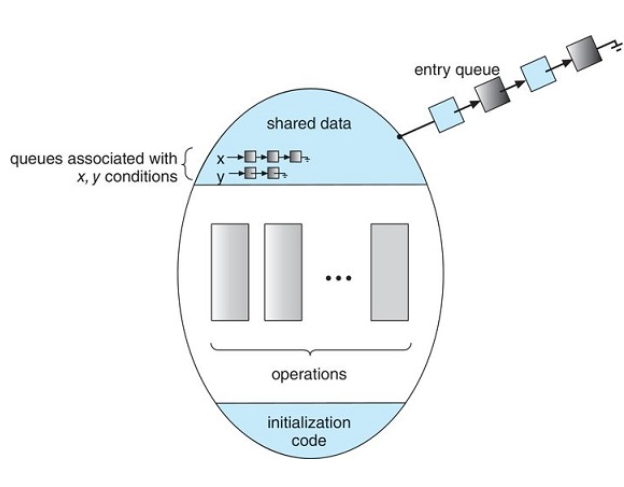
Monitors also need a condition construct which are declared in the style condition x,y;
- The only operations that can be invoked on a condition variable are
wait()andsignal() - the operation
x.wait()means that the process that is invoking this opeartion is suspended until another process invokesx.signal() - The
x.signal()operation resumes exactly one suspended process
Schematic View of a Monitor
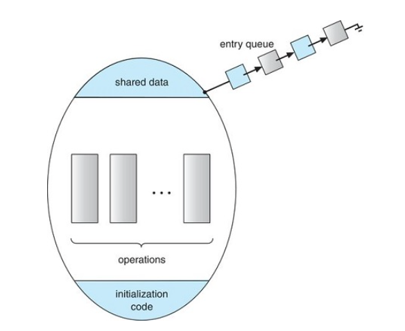
Monitor with condition variables
Dining-Philosophers Solution Using Monitors
The monitor solution imposes the restriction that a philosopher may pick up their chopsticks only if both are available
- To code the solution, we need to distinguish among three states in which we might find a philosopher,
enum{thinking,hungry,eating} state[5]the array is for the state of 5 philosophers which can be in any of the above states - Philosopher i can set the variable state[i] = eating only if his two neighbors are not eating
(state[(i+4]%5 !=eating) && (state[(i+1)%5] !=eating) - we also need to declare
condition self[5]where philosopher i can delay himself when he is hungry but is unable to obtain the chopsticks he needs
monitor dp{
	enum{THINKING,HUNGRY,EATING} state[5];
	condition self[5];

	void pickup(int i){
		state[i] = HUNGRY;
		test(i);
		if(state[i]!=EATING)
		self[i].wait()
	}
	void putdown(int i){
		state[i] = THINKING;
		test((i+4)%5);
		test((i+1)%5);
	}
	void test(int i){
		if((state[(i+4)%5] != EATING)&& (state[(i+1)%5] != EATING) && state[i] == HUNGRY ){
		state[i]= EATING;
		self[i].signal();
		}
	}
	initialization(){
	for(int i=0; i<5; i++){
		state[i]= THINKING;
		}
	}
}
Write processes.cpp where:
A parent process writes a message to:
cout << “okay?” << endl;
But stdout is redirected to pipe 1(0). dup2(fd[0][1],1)
A child process read the above message from
cin >> message;
But stdin is redirected to pipe 1(0). //std in = dup2(x,0)
dup2(fd[0][0],0)
A child process then writes a response to:
cout << “yes!” << endl;
But stdout is redirected to pipe 2(1). //std out = dup2(x,1)
dup2(fd[1][1],1)
A parent process reads the above response from
cin >> response;
But stdin is redirected to pipe 2.
dup2(fd[1][0],0)
Then, the parent write this response to stderr like:
cerr << response;
#include <sys/types.h>   // for fork, wait
#include <sys/wait.h>    // for wait
#include <unistd.h>      // for fork, pipe, dup, close
#include <stdio.h>       // for NULL, perror
#include <stdlib.h>      // for exit

#include <iostream>      // for cout

using namespace std;

int main( int argc, char** argv ) {
  int fd[2][2];   // fd[0][] parent-->child; fd[1][] child-->parent
  int pid;        // process ID
  char response[10], message[10];

  if ( pipe( fd[0] ) < 0 ) { // parent wants to create pipe fd[0]
    perror( "pipe fd[0] error" );
    exit( -1 );
  }
  if ( pipe( fd[1] ) < 0 ) { // parent also wants to create pipe fd[1]
    perror( "pipe fd[1] error" );
    exit( -1 );
  }
  if ( ( pid = fork( ) ) < 0 ) {
    perror( "fork a child: error" );
    exit( -1 );
  }
  if ( pid > 0 ) { // parent
    close( fd[0][0] ); //close parent-->child read pipe as it's not used
    dup2( fd[0][1], 1 ); //dup2 redirect pipe write 0 to stdout

    close( fd[1][1] ); //close child--> parent write pipe as it's not used
    dup2( fd[1][0], 0 );//redirect read of pipe 1 to std in

    cout << "okay?" << endl;
    cin >> response;
    cerr << response;
  }
  else { // child
    close( fd[0][1] ); //close parent-->child write pipe
    dup2( fd[0][0], 0 ); //duplicate parent-->child read pipe to stdin

    close( fd[1][0] ); //close child--> parent read pipe
    dup2( fd[1][1], 1 );//redirect write pipe of childparent to std out

    cin >> message;
    cout << "yes!" << endl;
  }
}
Deadlocks
In a multiprogramming environment, several processes may compete for a finite number of resources.
A process requests resources, and if the resources are not available at that time, the process enters a waiting state.
Sometimes, a waiting process is never again able to change state because the resources it has requested are held by other waiting processes. This situation is known as a Deadlock
System model
A system consists of a finite number of resources to be distributed among a number of competing processes.
The resources are partitioned into several types, each consisting of some number of identical instances.
Under a normal mode of operation, a process may utilize a resource only in the following sequence.
- Request: If the request cannot be granted immediately(for example, if the resource is being used by another process) then the requesting process must wait until it can acquire the resource.
- use: The process can operate on the resource(for example, if the resource is a printer, the process can print on the printer)
- Release: the process releases the resource.
Deadlock Characterization
In a deadlock, processes never finish executing and system resources are tied up preventing other jobs from starting
Necessary conditions for deadlocks:
A deadlock situation can arise if the following four conditions hold simultaneously in a system
- Mutual Exclusion: At least one resource must be held in a non-sharable mode, or, only one process at a time can use the resource. Any process that requests that resource must be delayed until the resource has been released.
- Hold and wait: A process must be holding atg least one resource, and waiting to acquire additional resources that are currently being held by other processes.
- No preemption: Resources cannot be preempted. A resource can only be released voluntarily by the process holding it. After that process has completed it's task.
- Circular Wait: A set {
} of waiting processes must exist such that is waiting for a resource held by , is waiting for a resource held by ..., is waiting for a resource held by .
Resource Allocation Graph
Deadlocks can be described more precisely in terms of a directed graph called a system resource-allocation graph.
This graph consists of a set of
A directed edge from thread
Generally we represent each thread
Since resource
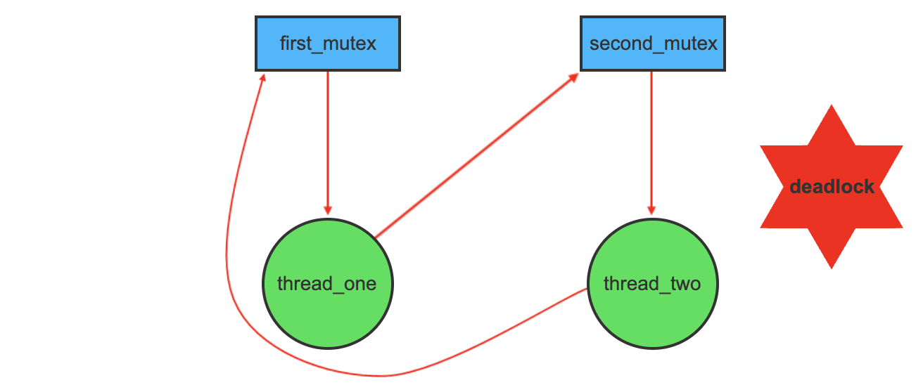
If the graph contains no cycles, then no process in the system is deadlocked. HOWEVER, if a graph contains a cycle, a deadlock may exist.
Methods for handling Deadlocks
In general, there are three ways we can handle deadlocks:
- Prevention: We can use a protocol to prevent or avoid deadlocks, ensuring that the system will never enter a deadlock state
- Recovery: We can allow the system to enter a deadlock state, detect it, and recover.
- Ignore it: We can ignore the problem altogether, and pretend deadlocks never occur in the system. (This is used in most operating systems)
To ensure deadlocks never occur, the system can either use a deadlock prevention, or a deadlock avoidance scheme
Deadlock Prevention
Provides a set of methods to ensure at least one of the criteria for deadlock cannot hold
Deadlock Avoidance
Requires the operating system be given in advance, additional information concerning which resources a process will request during its lifetime.
With this knowledge, it can decide for each request whether or not the process should wait.
Recovery
The system can provide an algorithm that examines the state of the system to determine whether or not a deadlock has occurred and an algorithm to recover from the deadlock.
Ignorance
If a system neither ensures that a deadlock will never occur nor provides a mechanism for deadlock detection and recovery then we may arrive at a situation where the system is in a deadlocked state yet has no way of recognizing what has happened.
In this case, the undetected deadlock will result in the deterioration of the systems performance, because resources are being held by processes that cannot run and because more and more processes, as they make requests for resources, will enter a deadlocked state.
Eventually, the system will stop functioning and will need to be restarted manually.
Deadlock Prevention
For a deadlock to occur, all four of the following must be present:
- Mutual Exclusion
- Hold and Wait
- No Preemption
- Circular Wait
By ensuring any one of the above cannot happen, you can prevent Deadlocks.
Mutual Exclusion
The mutual condition must hold for non-sharable resources
eg: A printer cannot be simultaneously shared by several processes.
Sharable resources, in contrast, do not require mtuually exclusive access and thus cannot be involved in a deadlock.
For example, Read-only files. If several processes attempt to open a read-only file, there will be no problem.
In general we cannot prevent deadlocks by denying the mutual exclusion condition because some resources are inherently non-sharable
Hold and Wait
To ensure the hold-and-wait condition never occurs, we must guarantee that whenever a process requests a resource, it does not hold any other resources.
One protocol that can be used requires each process to request and be allocated all its resources before it begins execution.
An alternative protocol allows a process to request resources only when it has none. A process may request some resources and use them. Before it can request any additional resources, however, it must release all the resources that it's currently allocated.
Both of these protocols have two main disadvantages
- Resource Utilization may be low
- Starvation is possible
No Preemption
To ensure this condition does not hold, we can use the following protocol:
If a process is holding some resources and requests another resource that cannot be immediately allocated to it, then all resources currently being held are preempted
Alternatively, if a process requests some resources, we first check whether they are available. If they are, we allocate the. If they are not, we check whether they are allocated to some other process that is waiting for additional resources. If so, we preempt the desired resources from The waiting process and allocate them to the requesting process.
This protocol is often applied to resources whose state can be easily saved and restored later such as registers and memory space.
Circular Wait
A way to ensure that this condition never holds is to impose a total ordering of all resource types and to require that each process requests resources in an increasing order of enumeration.
Example: Suppose some process, P1, is allocated resource R5. Now, if P1 requests for resources R3 and R4 (which are less than R5), the requests will NOT be granted. Only requests for resources that are greater than R5 will be granted.
Developing a resource hierarchy does not itself prevent deadlocks. It is up to developers to write programs that follow that ordering.
Deadlock Avoidance
An alternative method for avoiding deadlocks is to require additional information about how resources are to be requested.
For example: In a system with one tape drive and one printer, the system might need to know that process P will request the tape drive and then the printer before releasing both resources, whereas process Q will request first the printer and then the tape drive.
With this knowledge of the complete sequence of requests and releases for each process, the system can decide for each request whether or not the process should wait in order to avoid a possible future deadlock
Each request requires that in making this decision the system consider the resources currently available, the resources currently allocated to each process, and the future requests and releases of each process.
Safe State: A state is safe if the system can allocate resources to each process(up to its maximum) in some order and still avoid a deadlock.
A system is in a safe state only if there exists a safe sequence. A sequence of processes <
A safe state is not a deadlocked state, however not all unsafe states are deadlocked.
For example, lets say you have 12 resources and three threads,
| Maximum Needs | Current Needs | |
|---|---|---|
| 10 | 5 | |
| 4 | 2 | |
| 9 | 2 |
at time
A system can go from safe to unsafe pretty easily. For instance, if at time
Additionally, If thread
Resource Allocation Graph Algorithm
If we have a resource-allocation system with only one instance of each resource type, we can use a variant of the resource-allocation graph for deadlock avoidance. In addition to the request and assignment edges already described, we can introduce a new type of edge, called a claim edge. A claim edge
The resources must be claimed a priori in the system, or before thread
Suppose that thread
If no cycle exists, the allocation of resources will leave the system in a safe state. If a cycle is found, the allocation will put the system in an unsafe state. in that case, thread
Example:
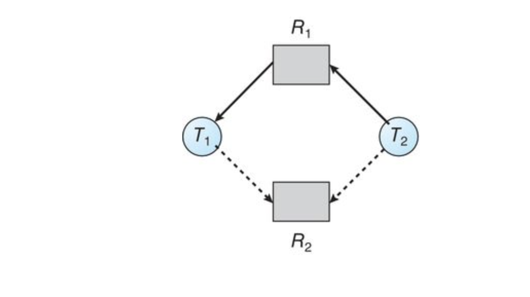
Suppose that
An unsafe state in the resource-allocation graph
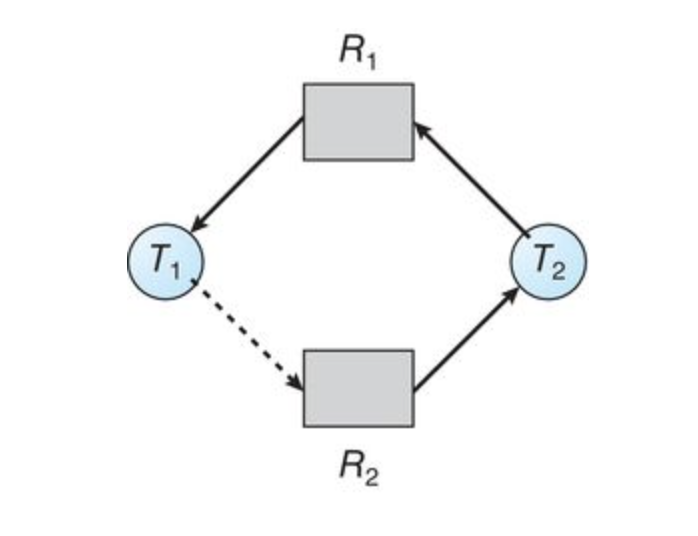
This only happens when there is one instance of a resource
Memory Management
The main purpose of a computer system is to execute programs
During executions, programs, together with the data they access, must be in main memory (at least partially).
Main Memory
In CPU scheduling, we see how the CPU can be shared by a set of processes. As a result of this, we see that CPU utilization, as well as speed of the computers response to its users can usually be improved
To realize this improvement however, we must keep several processes in memory. Memory must be shared**
Basic Hardware
Memory consists of a large array of words or bytes, each with its own address
A CPU fetches instructions from memory according to the value of the program counter
These instructions may cause additional loading from and storing to specific memory addresses
A typical instruction-execution cycle first fetches an instruction from memory, the instruction is then decoded and may cause operands to be fetched from memory. After the instruction has been executed on the operands, results may be stored back in memory
A CPU can only access from:
- registers
- main memory
There are machine instructions that take memory addresses as arguments but none that take a disk address
Therefore, any instructions in execution and any data used by the instructions must be in either registers or main memory. If data is not in memory, they must be moved there before the CPU can operate on them.
Cycle time for accessing memories
- Registers: Accessible within one cycle of the CPU clock. Most CPUs can decode instructions and perform simple operations on register contents at the rate of one or more operations per clock tick
- Main Memory: Access may take many cycles of the CPU clock to complete. Normally, the CPU must stall, since it does not have data required to complete the instruction before executing
Generally, another fast memory is placed between main memory and the registers. This is called the cache
Protection of OS from unauthorized access
the operating system must be protected from access by user processes. Additionally, user processes must be protected from one another.
This protection must be provided by the hardware.
To do this, we ensure that each process has a separate memory space. To do this, we need the ability to determine the range of legal addresses that the process may access and to ensure that the process can easily access only these legal addresses
This is done with two registers. The base register and the limit register.
- Base Register: Points to the bottom of the address space (Smallest Legal Physical Memory Address)
- Limit Register: Holds the size of the address space(Specifies the size of that range)
The base and limit registers can only be loaded by the operating system which uses a special privileged instruction
Since privileged instructions can only be executed in kernel mode, and since only the operating system operates in kernel mode, only the operating system can load the base and limit registers.
This scheme allows the operating system to change the value of the registers but prevents user programs from changing the registers contents.
Address binding
Usually a program resides on a disk as a binary executable file
To be executed, the program must be brought into memory and placed within a process
Depending on the memory management in use, the process may be moved between the disk and memory during its execution
The processes on the disk that are waiting to be brought into memory for execution form the input queue
Flow goes like this:
input queue -> select a process -> loads it into memory. -> executes and accesses instructions and data from memory -> process terminates ->memory space is declared available
Most systems allow a user process to reside in any part of the physical memory
Though the address space of a computer starts at 00000, the first address of the user space does not need to start there
In most cases, a user program will go through several steps during compile time, load time, execution time before being executed.
- Source program: addresses are generally symbolic
- Compiler: typically binds these symbolic addresses to relocatable addresses (such as 14 bytes from beginning of this module)
- Linkage or Loader: Binds the relocatable address to absolute address
Logical Vs Physical Address Space
- Logical Address: An address generated by the CPU
- Physical Address: An address seen by the memory unit, the one loaded into the memory address register of the memory.
We often refer to logical addresses as Virtual Addresses
- Logical Address Space: The set of all logical addresses generated by a program.
- Physical Address Space The set of all physical addresses corresponding to these logical addresses
How do we map these?
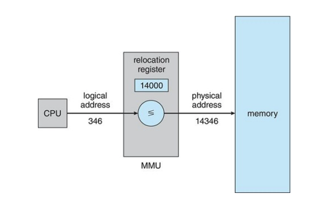
The runtime mapping from virtual to physical addresses is done by a hardware device called the Memory-Management Unit(MMU)
Dynamic Relocation using a Relocation Register
Dynamic Loading
The entire program and all data must be in physical memory for a process to execute. This means that the size of a process is limited by the size of physical memory
To obtain better memory-space utilization we can use dynamic loading
With dynamic loading a routine is not loaded until it's called.
All routines are kept on disk in a relocatable load format
The main program is loaded into main memory and executed
When a routine needs to call another routine, the calling routine first checks to see whether the other routine has been loaded
If it has not, the relocatable linking loader is called to load the desired routine into memory and update the program's address tables to reflect this change.
Then control is passed to the newly loaded routine.
Dynamic loading does not require special support from the operating system. It is the responsibility of the users to design their programs to take advantage of such a method
Dynamic Linking and Shared Libraries
When a program runs, it needs to use certain system libraries
- Static Linking: system language libraries are treated like any other object module and are combined by the loader into the binary program image. This is very wasteful of disk space and main memory
- Dynamic Linking: The system check to see if the needed routine is already in memory. If not, the routine is loaded into memory. It's similar to dynamic loading, but it's postponed until execution time.
Windows uses DLL files, or dynamic linked libraries.
With dynamic linking, a stub is included in the image for each library routine reference.
- stub: a small piece of code that indicates how to locate the appropriate memory-resident library routine or how to load the library if the routine is not already present.
when a stub is executed, it check to see if the needed routine is already in memory, if not, the program loads the routine into memory.
Either way, the stub replaces itself with the address of the routine and executes the routine
This means, the next time that particular code segment is reached, the library routine is executed directly, incurring no cost for dynamic linking.
Swapping
A process must be in memory to be executed
However, a process can be swapped temporarily out of memory to a backing store and then brought back into memory for continued execution.
A backing store is a computer storage device, usually a disk, that provides additional storage space for information so that it can be accessed and referred to when required and may be copied into the processor if needed.
Example:
In a multiprogramming environment with a round-robin CPU scheduling algorithm:
When a quantum expires, the memory manager will start to swap out the process that just finished and to swap another process into the memory space that has been freed.
The processes removed from scheduling may be placed in the backing store
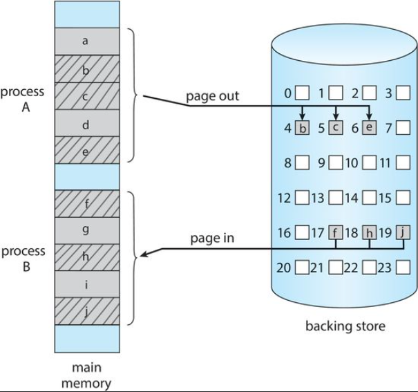
Memory Space when Swapping Happens
Normally, a process that is swapped out will be swapped back into the same memory space it previously occupied
However, this heavily relies on the address binding method
If the binding is done at assembly or load time, the process can not be easily moved to a different location
If binding is done at execution time, the process can be swapped into a different memory space because physical addresses are computed during execution time.
Backing Store
The backing store is commonly a fast disk drive
- It must be large enough to accommodate copies of all memory images for all users
- It must provide direct access to these memory images
- The system maintains a ready queue consisting of all processes whose memory images are on the backing store or in memory and are ready to run
- Whenever the CPU scheduler decides to execute a process, it calls the dispatcher
- The dispatcher then check to see whether the next process in the queue is in memory
- If not, the dispatcher swaps out a process currently in memory and swaps in the desired process.
- It then reloads registers and transfers control to the selected process.
Memory Allocation
We divide memory into several fixed sized partitions, each partition contains one process.
When a partition is free, a process is selected from the input queue and is loaded into the free partition.
When the process terminates, the partition becomes available for another process
Dynamic Storage Allocation Problem
The Dynamic storage allocation problem is as follows:
How do you satisfy a request of size
Solutions
First Fit
- We allocate the first hole that is large enough to accommodate the process
- Searching can start either at the beginning of the set of holes or where the previous first fit search ended.
- We can stop searching as soon as we find a free hole that is large enough to accommodate our process
Best Fit
- We allocate the smallest partition that is large enough to fit our process
- We must search the entire list, unless that list is ordered by size
- This leaves us with the smallest leftover hole
Worst Fit
This is the opposite of best fit.
- We allocate the largest partition that can hold our process
- We must still search the entire list unless sorted by size
- This leaves us with the largest leftover hole
Fragmentation
As process are loaded and removed from memory, the free memory space is broken into little pieces which results in fragmentation.
These are the free memory partitions that are left in between spaces
There are two types of fragmentations:
- External Fragmentation
- Internal Fragmentation
External Fragmentation
It exists when there is enough total memory space to satisfy a request, but the available spaces are not contiguous.
Storage is fragmented into a large number of small holes
This fragmentation problem can be severe. In the worst case, we could have a block of free(or wasted) memory between every two processes
If all these small pieces of memory were in one big free block instead, we might be able to run several more processes.
We cannot combine these segments are they are not contiguous
Internal Fragmentation
It occurs when memory blocks assigned to processes are larger than the process actually needs.
Some portion of memory is left unused as it cannot be used by a process
The solution for internal fragmentation is by using the "best fit" approach to memory allocation.
Solution to external fragmentation
Compaction is the solution to external memory fragmentation
Shuffle the memory contents so as to place all free memory together in one large block.
Paging
Paging is a memory management scheme that permits the physical address space of a process to be non-contiguous
Paging avoids the considerable problem of fitting memory chunks of various sizes into the backing store.
Most memory-management schemes suffer from this problem.
Basic Method of Paging
- Break physical memory into fixed sized blocks called frames
- Break logical memory into blocks of the same size called pages
- When a process is to be executed, its pages are loaded into any available memory frames from the backing store.
- The backing store is divided into fixed-size blocks that are the same size as memory frames.
Paging allows users to store processes in non-contiguous segments
Page Tables
Every address generated by the CPU is divided into two parts:
- a page number
- a page offset
The page table contains the base address of each page in physical memory
This base address is combined with the page offset to define the physical memory address that is sent to the memory unit
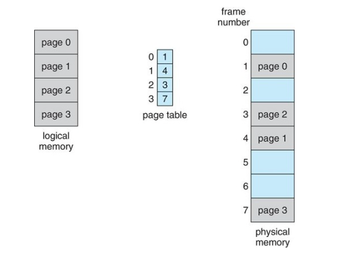
Translation of Logical Address To Physical Address using a Page Table
Every address generated by the CPU is divided into two parts:
- Page Number(p): Used as an index into a page table
- Page Offset(o): the displacement within the page and frame
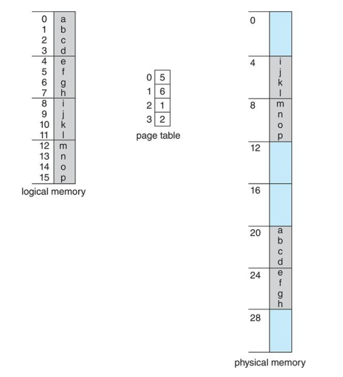
logical address to a physical address is
Hardware Implementation of a Page Table
- Case 1: Implement page table as a set of dedicated registers (only possible when page table is small)
- Case 2: Keep Page Table in main memory and a page-table base register (PTBR) points to the page table. (This increases the time required to access a user memory location as there are two memory accesses per byte. One to access the page table, and one to access the actual data)
- Case 3: Use a TLB (Translation Lookaside Buffer)
TLB
The TLB is an associative, high-speed memory
It consists of two parts:
- A Key
- A Value
When the associative memory is presented with an item, the item is compared with all keys simultaneously
If the item is found, the corresponding value field is returned
This is a very fast search
TLB with Page Table
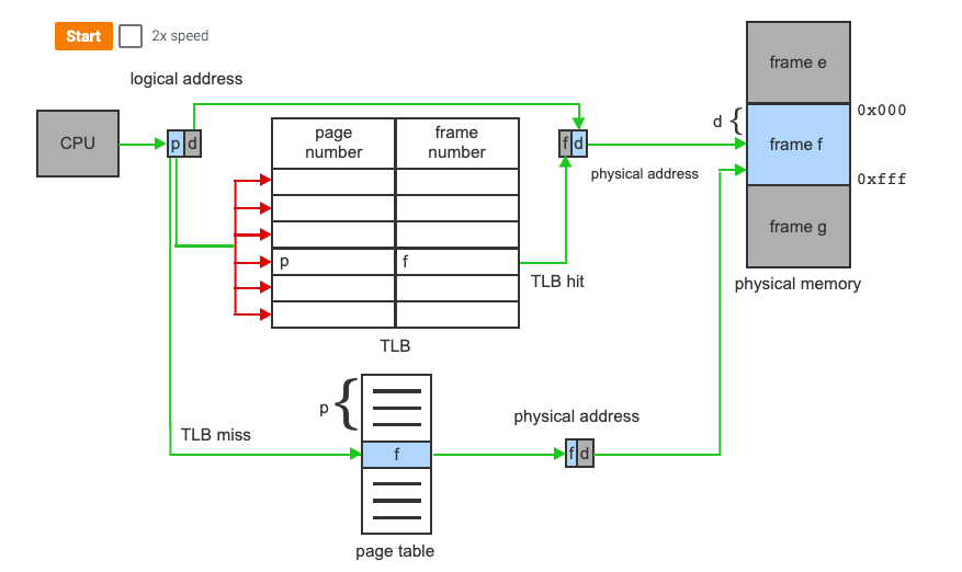
- The TLB contains a small portion of the page-table entries
- When a logical address is generated by the CPU, its page number is presented to the TLB
- If the page number is found, its frame number is immediately available and used to access that location in memory (This is a TLB Hit)
- If the page number is Not in the TLB, a memory reference to the page table must be made (TLB MISS)
- When the frame number is obtained, we can use it to access memory
- We also add the page number and frame to the TLB so they will be found more quickly on the next memory search
If an entry in the TLB is not found, once it goes out to main memory, it may replace a prior entry in the TLB (This is sometimes done with LRU or Least Recently Used)
Page Table Entries
- The valid/invalid bit is actually present in main memory. If it is not present, it is known as a **page fault** - If the page is not present in main memory, the Present/Absent bit is set to 0 - The protection bit is also known as the Read/Write bit and sets the permission for reading or writing. The bit is set to 0 if only read is allowed, The bit is set to 1 if both read and write are allowed - The referenced bit sets whether or not the page has been referenced within the last clock cycle (set to 1 if true) - The caching bit is used for enabling or disabling the caching of the page when disabled, it's set to 1 - The Dirty bit is also known as the modified bit, whether it's been modified or not. If the page has been modified it is set to 1 This helps in avoiding unnecessary writes to the secondary memory when a page is being replaced by another page.Shared Pages
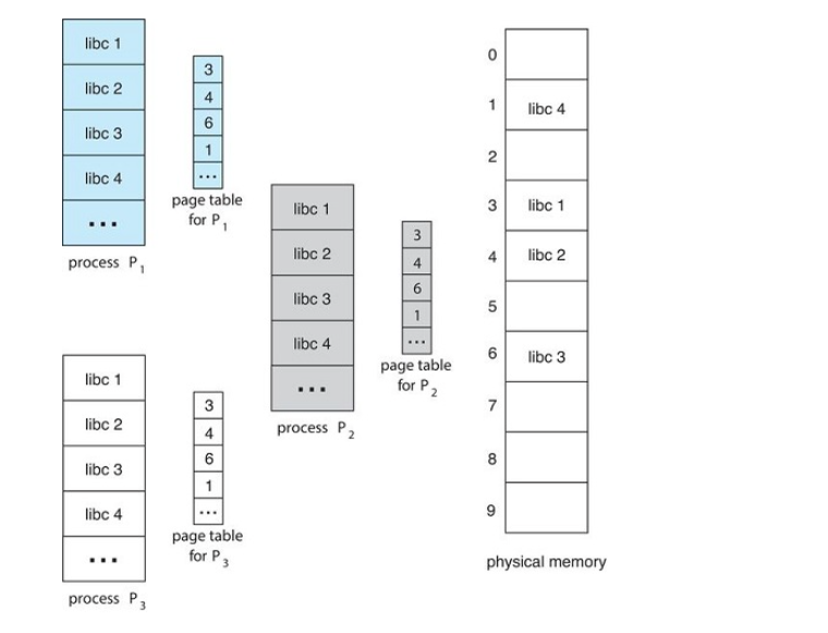
An advantage of paging is the possibility of sharing common code.
Consider a system that supports 40 users, each of whom executes a text editor.
If the text editor consists of 150kb of code and 50kb of data space,
With non-shared memory, we would need 200*40 or 8000kb of space.
However, if the text editor was in shared memory, we would only need 150kb + 50*40 or...2150kb
With shared pages, each process has its own copy of registers and data storage to hold the data for the process's execution
The data for two different processes will obviously be different.
Hierarchical Paging
Most modern computer systems support a very large logical address space (
In such an environment, the page table itself becomes excessively large
For example, imagine a system with:
32-bit logical address space
If page size = 4kb (
Then a page may consist of up to (
If each entry consists of 4 bytes, each process may need up to 4mb (4* 1 million) of physical address space
If we try to allocate a page table of this size contiguously in main memory, we will run into problems
The solution
Divide the page table into smaller sizes.
This is known as multi-level paging
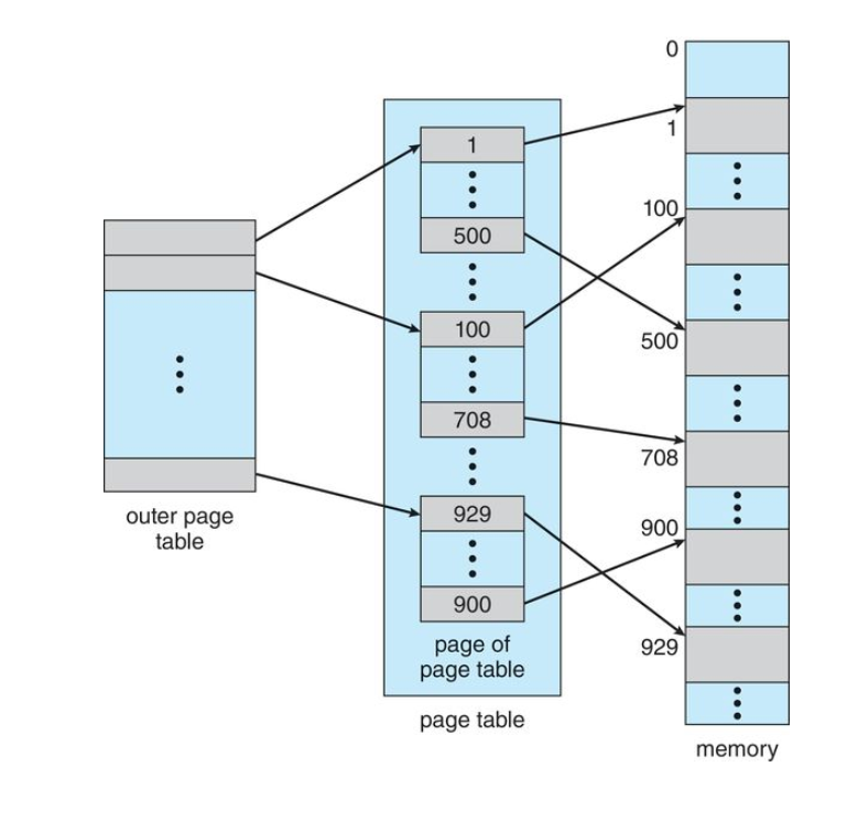
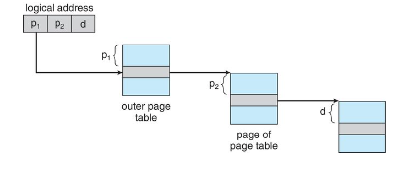
Use a two-level paging algorithm, in which the page table itself is also paged
A two level page table scheme
Hashed Page Tables
Hashed page tables are used for handling address spaces larger than 32 bits (or large address spaces)
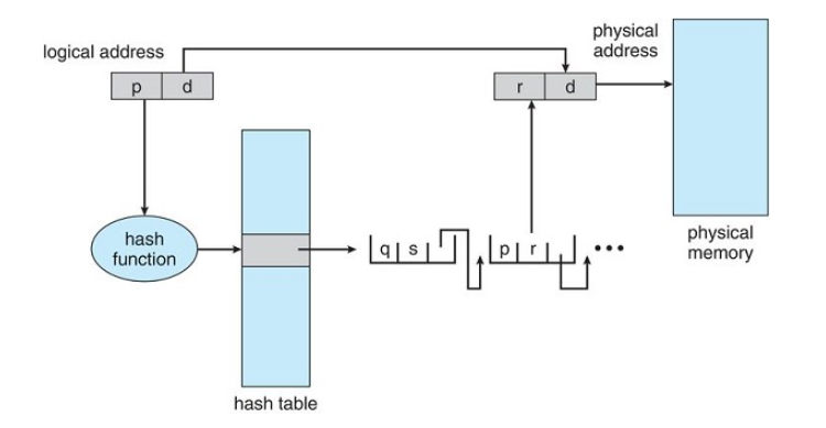
- The hash value is the virtual page number (the page number in the logical address)
- Each entry in the hash table contains a linked list of elements that has to the same location
Each node consists of three fields - Virtual page number
- the value of the mapped page frame
- a pointer to the next element in the linked list
The Algorithm
- The virtual page number in the virtual address is hashed into the hash table
- The virtual page number is compared with field 1 in the first element in the linked list.
- If there is a match, the corresponding page frame(field 2) is used to form the desired physical address.
- If there is no match, the linked list is walked searching for a virtual page number
Clustered Page Tables
This is a variation of the hashed page table that is most applicable to 64bit addresses
- It's similar to the hashed page tables except that each entry in the hash table refers to several pages rather than a single page
- Therefore, a single page table entry can store the mappings for multiple physical-page frames
- Clustered page tables are particularly useful for sparse address spaces, where memory references are non-contiguous and scattered throughout the address space
Inverted Page Tables
In most operating systems, a separate page table is maintained for each process. For 'n' number of processes, there will be 'n' number of page tables.
For large processes, there would be many pages and for maintaining information about these pages, there would be too many entries in their page tables which itself would occupy a lot of memory.
This means, memory utilization is not efficient is a lot of memory is wasted in maintaining the page tables themselves
Inverted page tables solve this problem
Implementation
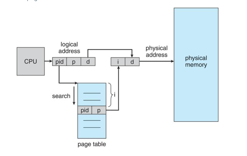
An inverted page table has one entry for each real page(or frame) of memory
Each entry consists of the virtual address of the page stored in that real memory location, with information about the process that owns that page.
This means, only one page table exists in the system, and it only has one entry for each page of physical memory.
With this, each virtual address consists of a triple with three fields
- process-id
- page-number
- offset
Each inverted page table entry is a pair
- process-id
- page number
When a memory reference occurs, part of the virtual address, consisting of (process-id, page number) is presented to the memory subsystem
The invertaed page table is then searched for a match
If a match is found, say at entry 'i', then the physical address (i, offset) is generated
Advantages and Disadvantage
Advantage
- Reduces Memory Usage by having only one page table
Disadvantage
- Increased search time as inverted page table is sorted by physical address, but lookups occur on virtual addresses. The whole table may need to be searched to find a match
Segmentation
Segmentation is another non-contiguous memory allocation technique similar to paging
Unlike paging however, in segmentation, the processes are not divided into fixed pages
Instead, the processes are divided into several modules called segments which improves the visualization for the users.
Here, both secondary memory and main memory are divided into partitions of unequal sizes.
- A logical address space is a collection of segments
- Each segment has a name and a length
The addresses specify both the segment name and the offset within the segment
The user specifies the segment name and an offset to access that item in memory
In paging, the user only needs to specify a single address, which is partitioned by the hardware into a page number and an offset, all invisible to the programmer
For simplicity, segments are numbered and referred to by a segment number rather than a segment name.
Therefore, a logical address consists. of a two tuple:
- Segment-number
- Offset
To use this, we need a segment table
A segment table maps two dimensional user defined addresses into one dimensional physical addresses. This is done through the use of a segment table
Each entry in a segment table has a segment base and a segment limit
The segment base contains the starting physical address where the segment resides in memory and the limit specifies the size of the segment
Virtual Memory
The purpose of memory management is to keep many processes in memory simultaneously to allow multiprogramming. This can be difficult though as that tends to require that an entire process be in memory before it can begin executing. Therefore, the processes that can be loaded into main memory are often limited by the size of the main memory.
For example, if the size of main memory is 2gb, and a process requires 3gb...it becomes difficult to accommodate such processes in main memory. We can use methods such as dynamic loading but that generally requires extra precautions by the programmer.
What is Virtual Memory?
Virtual memory is a storage scheme where secondary memory can be treated as though it is a part of main memory and large processes can be stored in it. Only the part of the process that is actually needed for execution will be loaded to the actual main memory.
In most real programs, there is often code to handle unusual error conditions. Since these errors seldom, if ever, occur in practice, this code is almost never executed
Another examples, is arrays, lists, and tables. These are often allocated more memory than they actually need. An array may be declared 100 by 100 elements, even though it is seldom larger than 10 by 10 elements
Finally, an assembler symbol table may have room for 3000 symbols, although the average program has fewer than 200 symbols.
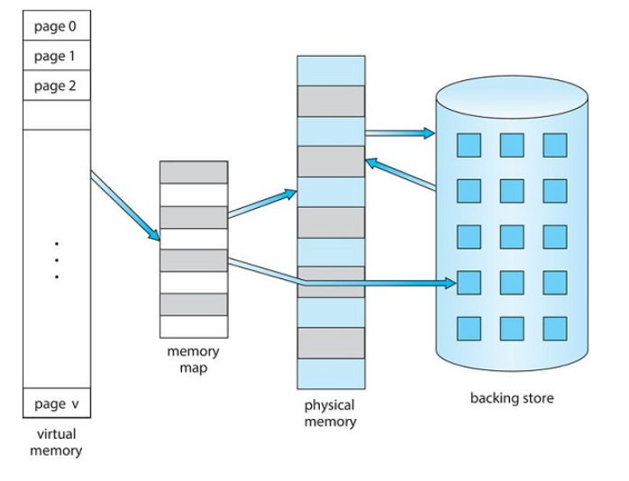
Benefits of being able to execute a program that is only partially in memory
- A program is longer constrained by the amount of physical memory that is available. Users are able to write programs for an extremely large virtual address space, simplifying the programming task
- Because each user program can take less physical memory, more programs can run at the same time. This gives us an increase in CPU utilization and throughput (it does not increase turnaround time or response time)
- Less I/O is needed to load or swap each program into memory, so each program runs faster.
Using virtual memory benefits both the system AND the user
Virtual memory involves the separation of logical memory as perceived by users from physical memory, this separation allows an extremely large virtual memory to be provided for programmers when only a smaller physical memory is available.
Demand Paging
How can an executable be loaded from disk to memory?
Possible Approaches
- Load the entire program into physical memory at program execution time.
- The problem with this solution is we may not initially need the entire program in memory. Think of a program that prompts the user for available options. Loading the entire program results in loading code for all options instead of what the user needs which wastes memory space.
- Load pages only as they are needed. Pages are loaded when they are demanded during program execution. Pages that are never accessed are never loaded into memory this is known as demand paging. Pages are demanded when they are needed
A demand paging system is similar to a paging system with swapping where processes reside in secondary memory(usually a disk)
When we want to execute a process, we swap it into memory.
Rather than swapping the entire process into memory, however, we use a lazy swapper
A lazy swapper never swaps a page into memory unless that page will be needed.
Since we are now viewing a process as a sequence of pages, rather than as one large contiguous space, the use of the term swapper is technically incorrect.
In connection with demand paging, the more appropriate term is pager
A swapper manipulates entire processes, whereas a pager is concerned with the individual pages of a process.
Hardware implementation of Demand Paging
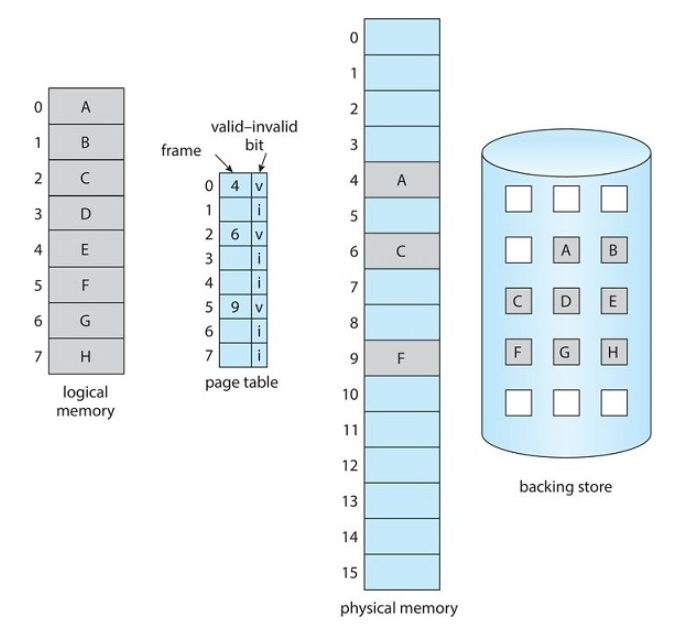
In order to implement demand paging with hardware, we need to be able to distinguish between pages that are in memory and the pages on the disk
To do this, we can make use of the Present/Absent (or Valid/Invalid Bit).
- If the bit is set to valid the page is both legal AND in main memory. By legal, it is a page that actually exists.
- If the bit is set to invalid, the page is either not in the logical address space of the process, or it is valid but is in the backing store
Page Table Entries
Page table entries for pages that are brought into main memory will be set as usual
Page table entries for pages that are not currently in memory will either be marked as invalid or contains the address of the page on disk in secondary memory
Page Faults
Page Fault: when a process tries to access a page that is not in main memory(or marked as invalid)
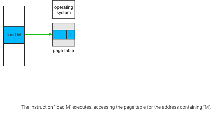
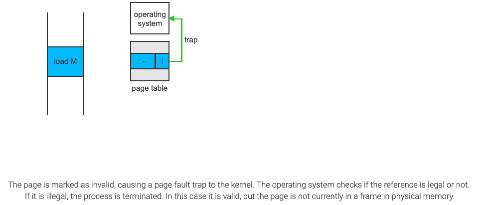
Access to a page marked as invalid causes a page-fault trap. The paging hardware will notice that the invalid bit is set, causing a trap on the operating system.
A page fault may occur at any memory reference.
- If the page fault occurs on the instruction fetch, we can restart by fetching the instruction again.
- If the page fault occurs while we are fetching an operand, we must fetch and decode the instruction again and then fetch the operand
Procedure for handling page faults
- We check an internal table, (usually kept within the Process Control Block) for this process to determine whether the reference was a valid or invalid memory access
- If the reference was invalid, we terminate the process
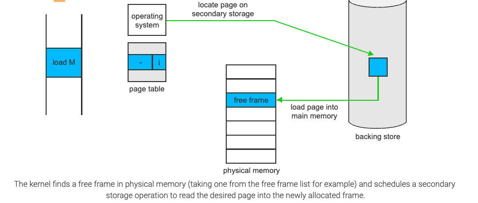
- If it was a valid memory access(legal, not in valid/invalid bit sense), but we have not yet brought in that page, we now page it in.
- We find a free frame(by taking one from the free-frame list)
- We schedule a disk operation to read the desired page into the newly allocated frame
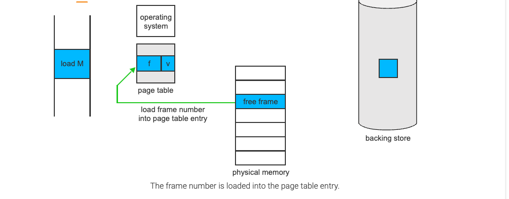
- When the disk read is complete, we modify the internal table kept within the process and the page table to indicate that the page is now in memory(set valid/invalid bit to 1)
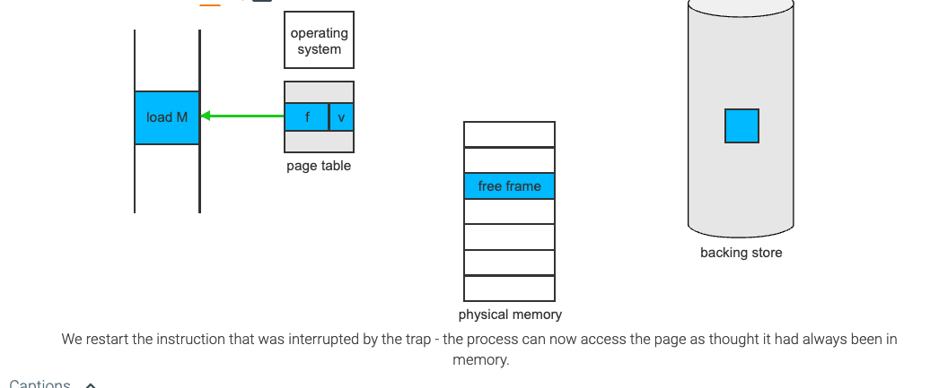
- We restart the instruction that was interrupted by the trap
The process can now access the page as though it had always been in memory
Demand Paging Performance
A computer systems performance can be significantly affected by Demand Paging
Memory Access time (ma) for most systems usually ranges from 10 to 200 nanoseconds
If there are no page faults, the Effective Access Time will be equal to the Memory Access Time
However, if a page fault occurs, we need to calculate the Effective Access Time
let
Then, effective access time =
There are three major components of the page-fault service time:
- Service the page-fault interrupt
- Read in the page
- restart the process
For example: If you have a memory access time of 200nanoseconds, and a page fault time of 8milliseconds(8,000,000 nanoseconds), and the probability of a page fault is 25% then you'd have
You can also create a formula out of it which would be
Copy On Write
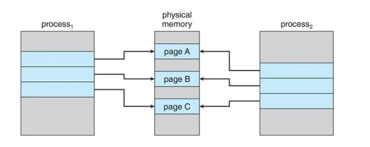
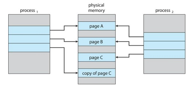
Copy on write (CoW) is a technique that is used for sharing virtual memory or pages. It's mostly used in conjunction with the fork() system call that is used for creating child processes
fork() will create a copy of the parent's address space for the child, duplicating the pages belonging to the parent.
Instead of duplicating the pages, we can make the parent and child processes share the common pages, and only create a copy when one of the processes (either child or parent) wants to write(modify) a page.
Before Process 1 modifies page C
After Process 1 modifies Page C
Problems with Demand Paging
With the help of demand paging we are increasing our degree of multi-programming by loading only the required pages into memory, hence facilitating the possibility of having more processes loaded into memory.
However, this could lead to an issue
Overallocation of memory
- suppose we have 40 frames in memory
- We have 6 processes each of which has 10 pages but uses only 5 at the moment.(5 pages of each will not be loaded)
- We can load these (6 x 5)=30 pages into memory
- So all the process are executing simultaneously
- We still have 10 free frames
Now, say all 6 processes want to use all of their pages (the full 10 each)
Now we need to load the additional 30 pages, however we only have 10 free frames
So what can the OS do?
- Terminate the process: Not ideal as it destroys the purpose of Demand Paging
- The operating system can instead swap out an entire process, freeing all it's frames and reducing the level of multiprogramming....good in certain circumstances
- We can make use of a page replacement technique(most common solution)
Page Replacement
Page Replacement is the technique of swapping out pages from physical memory when there are no more free frames available, in order to make room for other pages which have to be loaded to the main memory.
If a process wants to use/access a page which is not present in physical memory, it will cause a page fault. Now that page has to be loaded into memory
However, if there are no free frames available, how do we handle it?
- We can look for an occupied frame that is not being used currently
- We then free that frame by writing it's contents to the swap space (secondary memory)
- We update the page tables to indicate the page we removed is now no longer in memory
- We then load the page of the process that caused the page fault to occur in the freed frame
Steps of page replacement
- Find the location of the page to be loaded on the disk (in the backing store)
- If there is a free frame, use that frame by loading the page into the frame
- If there are no free frames, use a page-replacement algorithm to select a victim frame.
- Write the victim frame to the disk, and change the page and frame tables accordingly
- Read the desired page into the newly freed frame and change the page and frame tables.
- Restart the process
Victim Frame: The frame we are choosing to remove from physical memory so that we have a space for the page we are trying to swap in
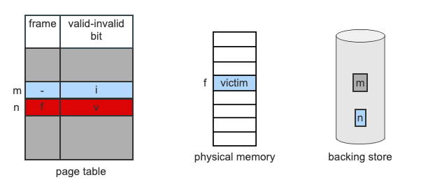
- Page n is not currently in memory and has been accessed by the current instruction. A page fault occurs, and there are no free frames. Frame f is selected as the victim.
- Frame f is currently holding page m. The OS writes the page to swap space on secondary storage, and frees the frame by marking m as invalid.
- The OS locates page n on the backing store and schedules an I/O transfer to DMA the contents into frame f.
- The transfer finishes. The OS changes the page table for n to point to frame f and that the frame is valid. The instruction is restarted and can now access the data it needs.
Page Fault Service Time When No Frames Are Free
- if no frames are free, two page transfers (one out and one in) are required
- This doubles the page-fault service time and increases the effective access time accordingly
We can reduce this time by making use of the modify(dirty) bit
The modify bit is set when a page has been modified
When page replacement has to be done on a page which is present in memory:
- if a modify bit is set - that means the page has been modified and we need to write the changes to the disk.
- If the modify bit is not set - that means that the page has not been modified and it is the same as the copy which is already present in the disk. In that case, we don't have to overwrite this page on the disk, reducing the overhead and the effective access time accordingly
FIFO Page Replacement
FIFO is the simplest page replacement algorithm
When page replacement has to be done, the oldest page in memory is chosen to be swapped out.
How do we maintain a record of the time that pages were brought into memory in order to figure out which page is the oldest?
- We don't have to record the times in a strict matter, instead, we can use a fifo queue that can hold all the pages that are in memory.
- When replacement has to be done, we choose the page at the head of the queue to be swapped out of memory
- when a new page is loaded into memory, we added it into the tail of the queue
FIFO Page-Replacement Algorithm

Belady's Anomaly
In general, we would think that if there are more frames, there will be fewer page faults
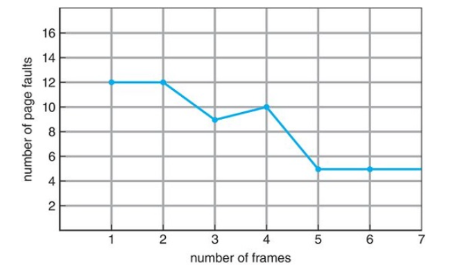
However, We see that as the number of frames increases, the number of page faults may increase as well. This is known as Belady's anomoly
Optimal Page Replacement

An optimal page-replacement algorithm has the lowest page fault rate of all the algorithms
- it will never suffer from Belady's anomaly
- It guarantees the lowest possible page fault rate for a fixed number of frames
To select a victim frame, we choose the frame that will not be used for the longest period of time.
The optimal page-replacement algorithm is difficult to implement because it requires future knowledge of the reference string.
Least Recently Used Page Replacement
It associates with each page the time of that page's last use
When a page must be replaced, the LRU chooses the page that has not been used for the longest period of time.
It can be thought of as an optimal-replacement algorithm but looking backwards in time

It's less optimal than the OPT algorithm, but more optimal than FIFO
It's generally considered a good algorithm and is used frequently
Implementation of Least Recently Used Page Replacement
An LRU page-replacement algorithm may require substantial hardware assistance.
How do we keep track of the pages that were least recently used?
- By using Counters
- By using a Stack
Using Counters
With Each Page Table Entry, we associate a time-of-use field and add a logical clock or counter to the CPU.
- The lock is incremented for every memory reference - Whenever a reference to a page is made, the contents of the clock register are copied to the time-of-use field in the page-table entry for that page. - This will give us the "time" of the last reference to each page - We then replace the time with the smallest time valueUsing a stack
- We maintain a stack of page numbers
- Whenever a page is referenced, it is removed from the stack and put on top
- That way, the most recently used page is always at the top of the stack and the least recently used will always be at the bottom.
- Since entries must be removed from the middle of the stack, it's best to implement this approach using a doubly linked list with a head and a tail pointer.
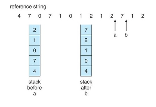
Additional-Reference Bits
LRU-Approximation Page Replacement
-
only a few computer systems provide the necessary hardware support for LRU Page Replacement
-
Some systems provide no support at all, so FIFO must be used
-
However, many systems provide support for LRU in the form of a Reference Bit
-
The reference bit (which is associated with each entry in the page table) for a page is set by the hardware whenever that page is referenced
Reference Bit Steps:
- Initially the operating system sets all reference bits for all pages to '0'.
- Whenever a page is referenced, the hardware sets the reference bit to '1'
- By checking these reference bits, we can tell which pages have been used and which haven't been used
We cannot, however, determine the order of use.
Therefore we need to use the "Additional Reference Bits Algorithm"
The additional reference bits algorithm is used to get an idea of the ordering information by recording the reference bits at regular intervals
How do we use it?
- We keep an 8-bit byte for each page in a table in memory
- at regular intervals(say, every 100 ms) a timer interrupt transfers control to the operating system
- The operating system shifts the reference bit for each page into the higher-order bit of it's 8-bit byte, shifting the other bits right by 1 bit and discarding the lower-order bit
- These 8-bit shift registers contain the history of page use for the last 8 time periods
Example
| Page No. | Shift Register Content | What It Means |
|---|---|---|
| P1 | 00000000 | The page has not been used for eight time periods |
| P2 | 11111111 | The Page has been used at least once in each period |
| P3 | 11000100 | The page has been used more recently than P4 |
| P4 | 01110111 | The page has been used less recently than P3 |
When the page is accessed, it sets the MSB (left most) to one.
Second Chance Algorithm
Another LRU-Approximation Page Replacement
- This is basically a FIFO replacement algorithm but with an additional feature
- When a page has been selected, we check its reference bit (1 if used, 0 if not)
- If there reference bit is 0, we replace the page
- If the reference bit is 1, we give a second chance to that page and move on to the next.
- When a page gets a SECOND CHANCE, it's REFERENCE BIT is reset to '0' and it's arrival time is reset to the current time
- If a page is given a second chance, it is not replaced until all other pages are either replaced or given their own second chances
- If a page is frequently used, it's reference bit will mostly be set to 1 and hence it will never be replaced
The implementation of the Second Chance Algorithm (also known as a clock algorithm) is usually implemented as a Circular Queue
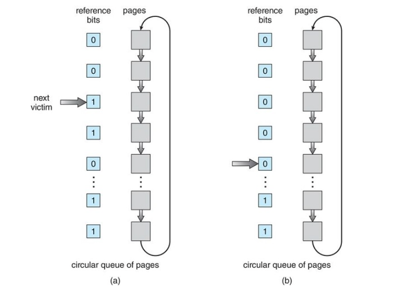
If all reference bits are set to 1, this algorithm will work like a FIFO algorithm
Enhanced Second Chance Algorithm
Another LRU-Approximation Page Replacement
In the enhanced second chance algorithm, we consider the reference bit and the modify bit as an ordered pair
There are four possible cases for the Enhanced Second Chance Algorithm:
| Reference Bit | Modify Bit | What It Implies | Remarks |
|---|---|---|---|
| 0 | 0 | The page was neither used recently nor modified | Best Page To Replace |
| 0 | 1 | This page was not used recently, but has been modified | This page was not used recently, but has been modified |
| 1 | 0 | The page was used recently but not modified | There are chances that this page will be used again soon |
| 1 | 1 | The page was used and modified recently | There are chances that this page will be used again soon and we will have to write this page to the disk if we replace it (worst case) |
Counting-Based Page Replacement
Maintain a counter that keeps a count of the number of references made to each page.
Using the counter, we formulate the following schemes:
- Least Frequently Used (LFU) Page-Replacement Algorithm
- Most Frequently Used (MFU) Page-Replacement Algorithm
Least Frequently Used
Counter - keeps a count of the number of references made to each page
- Pages which are least used will have a lower count
- Pages which are frequently used will have a higher count
- Replace the page with the lowest count
What is the problem with this?
Pages that were heavily used during the initial phase of the process would have higher counts and would remain in memory even though they may not be needed further
Solution
Shift the counts right by 1 bit at regular intervals forming an exponentially decaying average usage count
Most Frequently Used
Counter - keeps a count of the number of references made to each page
- Pages which are least used will have a lower count
- Pages which are frequently used will have a higher count
The page with the smallest count is probably the most recent page brought in and is yet to be used, therefore we do not replace the page with the least count.
Both these algorithms are expensive to implement and do not approximate the optimum page replacement well. Therefore, they are not often used.
Page Buffering Algorithms
In this algorithm, we maintain a pool of free frames
When A Page Fault Occurs:
- A victim frame is chosen
- The desired page is loaded into a frame from the free frame pool before the victim page is swapped out
- Once the victim page is swapped out and written to the disk, the victim frame will be added to the free frames pool
This allows the process to restart as soon as possible without waiting for the victim page to be written to the backing store
This idea can be modified by maintaining a pool of modified pages.
Whenever the paging device is idle:
- A modified page is selected and written to the disk
- it's modify bit is then reset.
This increases the probability taht a page will be clean when it's selected for replacement and will not need to be written back to the disk again.
Allocation of Frames
How do we allocate to various process the fixed amount(number of frames) of free memory that is available?
In a single user system:
- Memory Size = 128kb
- Page Size = 1kb
So number of frames will be 128
Suppose the operating system uses 30kb
Remaining frames for user processes = 98 (128-30)
These 98 frames would be available in the free frames list - If we're using demand paging, the first 98 page faults would get all free frames from the list
- When the free frames are exhausted, a page replacement algorithm would be used to replace a page from the occupied list of 98 with the 99th page.
Minimum number of frames
Constraints for allocation of frames:
- Unless there is page sharing, we cannot allocate more than the total number of available frames
- A minimum number of frames should be allocated to each process
- as the number of frames allocated to a process decreases, the page fault rate increases
- There should be enough page to hold all the different pages that any single instruction can reference.
- Suppose in a one-level indirect addressing, a load instruction on page 15 refers to an address on page 1 which is an indirect reference to page 22, here, 3 frames are needed per process(the three pages are 15,1,22, hence 3 frames).
So how do we decide how many frames to allocate?
- Suppose in a one-level indirect addressing, a load instruction on page 15 refers to an address on page 1 which is an indirect reference to page 22, here, 3 frames are needed per process(the three pages are 15,1,22, hence 3 frames).
Allocation Algorithms
Frame allocation algorithms help us in determining how many frames should be allocated to different processes in a multiprocessing environment
The 3 Most common allocation algorithms:
- Equal Allocation
- Proportional Allocation
- Priority Allocation
Equal Allocation
The frames are equally distributed among the processes (equal free frames/ num processes)
- if we have
number of frames - if we have
number of processes - we allocate
frames to each process
Say we have 98 frames and 5 processes
each process gets
The remaining 3 frames are kept as a free frame buffer pool
Problems
The memory requirements of each processes are not the same, some may need more than others, so by allocating equally we are not using resources efficiently.
In a system with 64 free frames with a frame size of 1kb, say we have two processes, P1(10kb) and P2(127kb).
We allocate
P1 only needs 10 frames however, so we waste 22. (
Proportional Allocation
The frames are distributed among the processes according to their sizes
- let
be the number of frames - let
be the size of process - The number of frames allocated to
is equal to where
In a system with 64 free frames with a frame size of 1kb, say we have two processes, P1(10kb) and P2(127kb).
The number of frames allocated to
The number of frames allocated to
Priority Allocation
The priority allocation algorithm is done using priorities or a combination of size and priorities rather than just the size of the processes
So we allocate more frames to processes with higher priorities so as to speed up their execution
Global vs Local Allocation
Page replacement algorithms can be classified into two broad categories:
- Global Replacement
- Local Replacement
This is important for deciding the way frames are allocated to different processes
Global Replacement
When a page fault occurs: - Processes are allowed to select replacement frames from the **set of ALL frames**, even if the frames are allocated to other processes >[!example] >If a process P1 is of higher priority than processes P2 and P3, and all of the frames of P1 are full and it now needs one more frame due to a page fault, it can take a frame allocated to either P2 or P3Problem with global allocation
Processes cannot control their own page fault rate
Local Replacement
When a page fault occurs: - Processes are allowed to select replacement frames **only** from the set of frames that is particularly allocated to them.Problems with local allocation
The memory utilization may not be optimal (eg an idle process that is not using all its frames)
Thrashing
Consider a process that doesn't have enough frames for its execution
Thrashing: when a process is spending more time in paging than actually executing the instructions.
Sever Performance Problems Due To Thrashing
The operating system monitors CPU utilization. If CPU utilization is too low, we increase the degree of multiprogramming by introducing a new process to the system.
- as processes are busy swapping pages in and out, the queue up for the paging device and the ready queue becomes empty.
- Since processes are now waiting for the paging devices, the CPU utilization decreases
- The CPU scheduler sees that the CPU utilization has decreased and in an attempt to increase CPU utilization, it increase the degree of multiprogramming by bringing in new processes
- These new processes try to take frames from the older processes which increases the number of page faults and increases the queue for the paging device
- The CPU utilization drops even further and the cycle continues
Thrashing causes system throughput to decrease massively
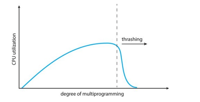
Thrashing can be reduced slightly by using local allocation, but this is not a great solution as it will still have many page faults. To reduce thrashing we need to use something like the Working-Set Model
Working-Set Model
How do we prevent thrashing?
We must provide a process with as many frames as it needs.
But how do we know how many frames it needs?
We make use of the working set strategy where it checks how many frames a process is actually using
The working set strategy defines the locality model of process execution
Locality model of process execution: As a process executes, it moves from locality to locality
Locality: A set of pages that are actively used together. A program is generally composed of several different localities which may overlap
Implementation of the working set model
To implement the working set model, we use a parameter
- The set of pages in the most recent
page references is the "working set" - If a page is in active use, it will be in the working set.
- If it is no longer being used, it will drop from the working set
time units after its last reference - Thus, the working set is an approximation of the program's locality

In the above image
Determining
The accuracy of our working set depends on the selection of
- if
is too large: It may overlap several localities - if
is too small: It may not cover the entire localities - if
is infinite: The working set is the set of pages touched during the process execution
The next important property of a working set is its size
The working set size of a process is denoted by
So, the total demand for frames in a system will be given by:
This will give the total demand for frames in a system.
If the total demand for frames(D) is greater than the total number of available frames(m) (aka
So what do we do if the demand is greater than the number of frames?
The operating system will select a process to suspend. The processes pages are swapped out and its frames are reallocated to the other processes. The suspended process can be restarted later.
The working-set strategy prevents thrashing while keeping the degree of multiprogramming as high as possible, which optimizes CPU utilization.
File System Interface
Storage Management
Programs have to be loaded to main memory for execution, however, the size of our main memory is limited and is usually too small to accommodate all the data and programs permanently. Because of this, the computer system must provide secondary story to back up main memory.
There are two main types of secondary storage:
- Internal: fixed inside the computer
- External: removable
Most computers use disks as the most common secondary storage device for both programs and data.
The File System provides a mechanism for: - Storage of data and programs on the disk
- Access to data on the disk
Files are mapped by the operating system to physical devices.
Files are a collection of related information defined by its creator. These files are normally organized into directories for ease of use.
Different storage devices vary in many aspects
For example:
- Some devices transfer a character or a block of characters at a time
- some can be accessed only sequentially
- some can be accessed randomly
- some transfer data synchronously
- some transfer data asynchronously
- some are dedicated while some are shared
- and some can be read-only or read-write
Because of the variation, the operating system needs to provide a wide range of functionality to applications, to allow them to control all aspects of the devices
Concept of Files
The operating system abstracts from the physical properties of its storage devices to define a logical storage unit - the file
A file is a logical storage unit
Files are mapped by the operating system onto physical devices
These physical devices are usually non-volatile(they will keep data after power is switched off) unlike main memory which is usually volatile
File definition:
A file is a named collection of related information that is recorded on secondary storage
From a User's perspective:
- A file is the smallest allotment of logical secondary storage
- data cannot be written to secondary storage unless they are within a file
Files represent both data and programs - this data can be numeric, alphabetic, alphanumeric, or binary
- the files may be free form, such as text files, of may be formatted rigidly
In general, a file is a sequence of bits, bytes, lines, or records, the meaning of which is defined by the file's creator and user.
Many different types of information may be stored in a file
File Attributes
Naming a file
A file is named for the convenience of its human users, and is referred to by its name.
A name is usually a string of characters. Eg myfile.c
When a file is named, it becomes independent of the process, the user, and even the system that created it
The attributes of files can vary from one OS to another but typically consist of the following:
- Name: the symbolic file name is the only information kept in human readable form.
- Identifier: A unique tag, usually a number, that identifies the file within the file system. It's the non-human-readable name for the file.
- Type: this information is needed for systems that support different types of files.
- Location: this information is a pointer to a device and to the location of the file on that device.
- Size: the current size of the file(in bytes, words, or blocks)and possibly the maximum allowed size are included in this attribute.
- Protection/Permission: access-control information determines who can do reading, writing, executing and so on.
- Creation Date: the date the file was created
- Last Modified Date: the date on which the file was last modified
- Owner: the information about who the owner of the file is.
The attributes of a file are stored in the File Control Bloc also known as the FCB.
File Operations
The operating system has to provide system calls to perform various file operations.
The common file operations are:
- Creating a file
- writing to a file
- reading from a file
- repositioning within a file
- deleting a file
- truncating a file
Creating A File
Steps for file creation:
- Check if space is available in the file system to create the new file, and find space on the disk for it.
- Make an entry for the file in the new directory.
Writing a File
Steps for writing a file:
- make a system call specifying both the name of the file and the information to be written to the file.
- With the given name of the file, the system searches for the file in the directory and locates it.
- A write pointer is maintained which points to the location in the file from where teh next write must take place.
- After the writing is done, the write pointer is updated
Reading a file
Steps for reading a file:
- Make a system call specifying both the name of the file and where(in memory) the next block of the file should be read.
- With the given name of the file, the system searches for the file in the directory and locates it
- A read pointer is maintained which points to the location in the file from where the next read must take place.
- After the reading is done, the read pointer is updated
- In general, most read and write operations use the same pointer.
Repositioning within a file(File seek)
Steps for repositioning within a file:
- The directory is searched for the appropriate file.
- The current-file-position pointer is repositioned to a given value.
Repositioning can be done without any I/O
Deleting a file
Steps for deleting a file:
- The directory is searched for the named file
- Once the directory is found, all the file space occupied by the file is released so that it can be used by other files.
Truncating a file
A user may want to erase the contents of a file but keep its attributes. Rather than forcing the user to delete the file and recreate it, this function allows all attributes to remain unchanged
Steps to truncate a file:
- Keep all the attributes of the file unchanged.
- The file length is reset to zero
- Release the file space.
Other file operations exist but are less common such as:
- appending new information to the end of an existing file
- renaming an existing file
- editing existing data on a file
- saving a file
- creating a copy of a file
- hiding a file
- sending a file
- printing a file
The open() System Call
Most of the common file operations involve searching the directory for the entry associated with the file name.
To avoid this constant searching, many systems require that an open() system call be made before a file is first used actively.
- The operating system keeps a small table, called the open-file table which contains information about all open files.
When a file operation is requested, the file is specified via an index into this table so no searching is required.
When the file is no longer being actively used, it is closed by the process and the operating system removes its entry from the open-file table.
File Types
When a file system or an operating system is designed, the file types that the operating system must should recognize and support must be considered
If an operating system recognizes a type of file, it can then operate on that file in standard ways
The most common technique for implementing file types is to include the type as part of the file name
This is specified by the file extension that appears after a period in the file name
Common file types
| File Type | Usual Extension | Function |
|---|---|---|
| Executable | exe, com, bin, or none | ready-to run machine language program |
| Object | obj, o | compiled machine language that has not been linked |
| Source Code | c, cpp, pas, java, asm, py | Source code in various languages |
| Batch | bat, sh | commands for the command interpreter |
| Text | txt, doc | textual data, documents |
| Word Processor | wp, doc, rtf | Various word processor formats |
| Library | lib, a | libraries of routines for programmers |
| Print or View | ps, pdf, jpg, png | ASCII or binary files in a format for printing or viewing |
| Archive | arc, zip, tar | Related files grouped into one file sometimes compressed for archiving or storage |
| Multimedia | mp3, mp4, avi | Binary files containing audio or A/v information |
Other ways of identifying file types:
In Mac OS X each file has a type that is specified with it to identify its type
In Unix systems, it uses a crude magic number stored at the beginning of some files to indicate roughly the type of file.
Access Methods
The information in files can be accessed in several ways. Some systems provide just one access method for files while other systems may support many access methods.
The two most common access methods are:
- Sequential Access
- Direct Access
Sequential Access
- the simplest access method
- information in the file is processed in order, one record after the other.
- most common editors, compilers, etc access files in this method

Read Operation
read next: reads the next portion of the file and automatically advances a file pointer which tracks the I/O location. The file pointer is advanced automatically
Write Operation
write next: appends to the end of the file and advances to the end of the newly written material (the new end of the file)
Direct Access
Also known as relative access
A file is made up of fixed length logical records that allow programs to read and write records rapidly in no particular order.
In direct access, the filed is viewed as a numbered sequence of blocks or records.
With direct access, there are no restrictions on the order of reading or writing for a direct-access file.
Direct-access files are great for immediate access with files of large amounts of information such as databases.
Simulation of sequential access on a direct-access file
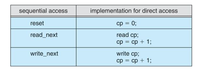
Read Operation
read n: read from the block number
Write Operation
write n: writes to the block number
The block number provided by the user to the operating system is normally a relative block number which is an index to the relative beginning of the file.
Directory Structure
The file system of a computer can be extensive as systems need to store huge number of files on a disk. To manage this, they must be organized properly.
Directories are used for organizing this data
Storage Structure
a disk or any large storage device can be used entirely for a file system, however, it's better to have multiple file systems on a disk or use parts of a disk for a file system, and other parts of the disk for things like swap space, raw dis space, etc
These parts are called partitions, slices, or minidisks, however partitions is the most common. A file system can be created on each of these parts of the disk, and these parts can be further combined to form a structure called a volume, and a file system can be created on these as well.
Volumes
- each volume can be thought of as a virtual disk.
- Volumes can store multiple operating system allowing the system to boot and run more than one operating system
- each volume that contains a file system must also contain information about the files in the system
- This information is kept in entries in a device directory
- a directory records information such as name, location, size, and type for all files in that volume
Operations That Can Be performed on a directory
- Search for a file
- Create a file
- Delete a file
- List a directory
- rename a file
- traverse the file system
Notice, some of these are the same operations that can be performed on a file.
Single-Level Directory
A single-level directory is the simplest directory structure
all the files are contained in the same directory

Advantages
- implementation is easy as there is just as single directory
- File operations like creating, reading, deleting, repositioning, renaming, etc are easily done
- searching for files will be fast if there are not many files and if they are small in size.
Disadvantages
- problems start arising when the number of files increases or when the system has multiple users
- all the files must have unique names since the files are in the same directory
- As the number of files increases:
- users will find it difficult to remember the names of each individual file
- searching for a file becomes difficult
Two-Level Directory
Each user has his or her own directory called the User File Directory(UFD)
Information about each UFD is stored in a system directory called the Master File Directory (MFD)
The MFD is indexed by user name or account number, and each entry points to the UFD for that user
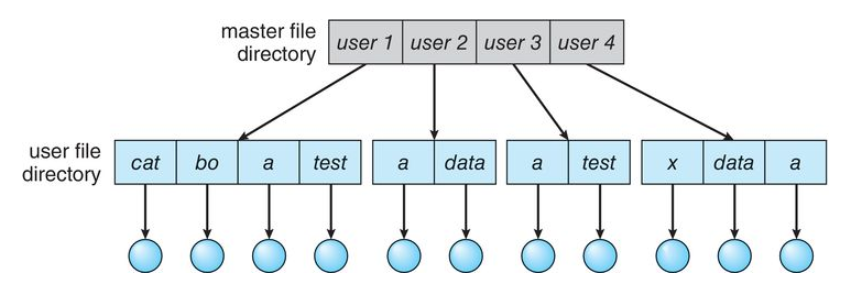
When a user refers to a particular file, only their own UFD is searched. Thus, different users may have files with the same file name as long as all the file names within each UFD are unique
Problems with Two-Level Directories
- Users are isolated from each other
- hen two or more users want to cooperate on a task and access the same file, it becomes difficult as the system doesn't permit this
- If users are allowed to access other users' files, then the files must be named with their complete path which specifies who is the owner of the file
- Every system has its own syntax for naming files and directories
- There are system files that have to be used by several users, when these files need to be accessed by a user, it will be searched for in that user's UFD. However, it won't be available there.
Tree Structured Directories
The natural generalization of a two-level directory structure is to extend the directory structure to a tree of arbitrary height
This generalization allows users to create their own subdirectories and organize their files accordingly
A tree is the most common directory structure
The tree has a root directory and every file in the system has a unique path name
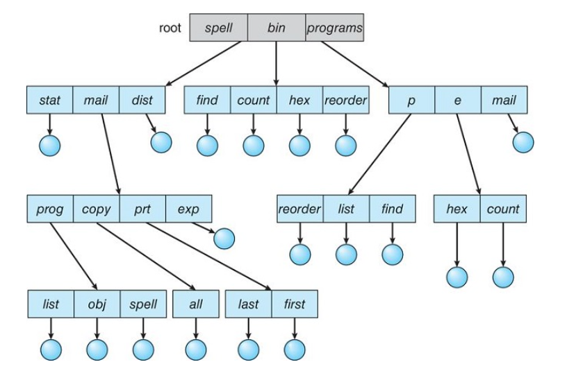
Current Directory
Each process will have a current directory which should contain most of the files that are of current interest to the process.
When reference is made to a file, the current directory is searched
If a file is needed that is not in the current directory, the user must either specify a path name or change the current directory to the directory holding the file
Path Names
There are two types of path names:
- Absolute: Begins at the root and follows a path down to the specified file, giving the directory names on the path.
- Relative: defines a path from the current directory.
Deleting a Directory
If the directory is empty, it's entry in the directory that contains it can simply be deleted.
If the directory is not empty:
- some systems will not allow deleting a directory unless it's empty, so to delete a directory, all it's files and subdirectories must be deleted first.
Acyclic-Graph Directories
Acyclic Graph Directories are good for sharing
An acyclic graph (a graph with no cycles) allows directories to share subdirectories and files.
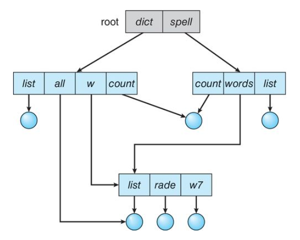
When people are working as a team, all the files they want to share can be put into one directory
The UFD of each team member will contain this directory of shared files as a sub directory
Implementation of shared files and subdirectories
- Links: a links is effectively a pointer to another file or subdirectory.
- Duplicating: duplicate all information about shared files in both sharing subdirectories. This entries are identical and equal. (A major concern here is maintaining consistency when the files are modified)
Problems with Acyclic Graph Structures
- Same file with many paths and names: A file may now have multiple absolute path names. Also, different file names may refer to the same filed. This may give the system a wrong count of files when trying to count the total number of files
- Deleting of Shared Files: if the file is deleted whenever someone deletes it, it will create "dangling pointers" to the non-existent file. If shared files are implemented using symbolic links, then deletion of a file by one user will delete only the link and wont affect the original file, however if the original file is deleted, it will leave the links dangling.
General Graph Directory
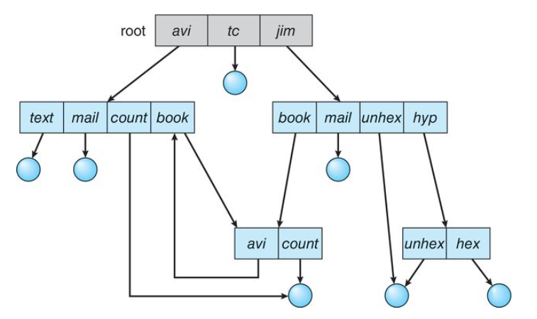
If we start with a two-level directory and allow users to create subdirectories, a tree-structured directory is usually the result
If we continue adding files and subdirectories in this way, the tree structure is preserved and continues
However, when we add links to an existing tree-structured directory, the tree structure is destroyed, resulting in a simple graph structure
Problems
- Searching for files: If cycles are allowed to exist in the directory, we want to avoid searching any component twice, for reasons of correctness as well as performance (think looping). A poorly defined algorithm may result in an infinite loop. A solution to this is to arbitrarily limit the number of directories that will be accessed during a search.
- Deleting files: in an acyclic-graph directory structure, if the reference count is 0 for any file, then that means there are no references to that file or directory and it can safely be deleted, however when cycles exist, the reference count may not be 0 even when it is no longer possible to refer to a director or file because of the possibility of self referencing cycles
Garbage Collection
Garbage Collection: A scheme to determine when the last reference has been deleted and the disk space can be reallocated.
- Traverse the entire file system and mark everything that can be accessed
- Traverse again a second time and free up all the unmarked cases from the first step
Garbage collection is extremely time consuming and thus rarely used.
Protection (Types of Access)
The information stored in a computer system must be kept safe from:
- Physical Damage (Reliability)
- Improper Access (Protection)
Physical Damage
File systems can be damaged by:
- hardware problems
- power surges/failures
- head crashes
- dirt
- extreme temperatures
- vandalism, etc
Reliability is generally provided by duplicate copies of files
Improper Access
- file systems must be allowed to be accessed only by authorized users
- in a single user system, the protection can be done easily
Types of Access
- Complete Protection: Access is prohibited to everyone except the owner
- Free Access: Access is provided to everyone
- Controlled Access: Can be provided by limiting the types of file access that can be made by different users
File Operations that may be controlled
- Read: Read from the file
- Write: write or rewrite the file
- Execute: loading the file into memory and executing it
- Append: write new information at the end of the file
- Delete: delete the file and tree its space for possible reuse
- List: list the name and attributes of the file
Other operations such as renaming, copying, and editing may also be controlled
Protection (Access Control)
The most common approach to the protection problem is to make access dependent on the identity of the user
We can implement this using an Access Control List (ACL)
With each file and directory, an access-control list is associated specifying user names and the types of access allowed for each user.
Access Control List
When a user requests access to a particular file, the operating system check the access list associated with that file
If that user is listed for the requested access, the access is allowed.
If not, a protection violation occurs and the user job is denied access to the file.
Problems with this approach:
- Constructing this list may be tedious especially if we do not know in advance the list of users in the system
- The directory entry, previously of fixed size, now needs to be of variable size resulting in more complicated space management
Solutions to this problem
Use a condensed version of the access list
Systems mostly recognize three classifications of users in connection with each file:
- Owner: The user who created the file is the owner
- Group: a set of users who are sharing the file and need similar access is a group or work group
- Other: all other users in the system
Permissions in a Unix System

On Linux/Unix, it goes user | group | other. If it's prepended by a d, it means "directory"
Permissions in a Windows System
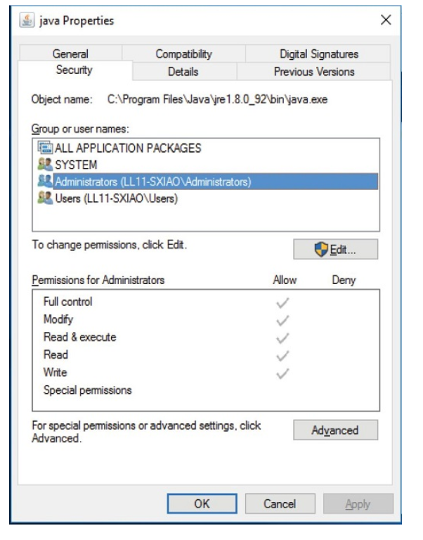
File System Implementation
Overview
The file system resides permanently on secondary storage, which is designed to hold a large amount of data in a permanent manner.
Different operating systems support different file system
for example:
- Unix: Unix File System
- Windows: FAT, FAT32, NTFS
Several on-disk and in-memory structures are used to implement a file system
On-disk structures
On disk, the file system may contain information about:
- How to boot an operating system stored there
- The total number of blocks
- The number and location of free blocks
- The directory structure
- Individual files
Boot Control Block
This is an on-disk structure
There is a boot control block for each volume
- Typically, the boot control block is the first block of a volume
- it contains information needed by the system to boot an operating system from that volume
- If the disk does not contain an operating system, this block can be empty
In the Unix file system, it is called a boot block
In NTFS it's called the boot sector
Volume control block
Each volume contains a volume control block that contains information such as:
- The number of blocks in the partition
- Free block count(how many blocks are free)
- Free-block pointers
- Free FCB(File Control Block) count and FCB pointers
In Unix this is called a superblock
In NTFS this is stored in the master file table
Directory Structure Per File System
In the Unix file system it includes file names and associated inode numbers
In NTFS, it is stored in the master table
Per-File FCB
This contains details about the file such as:
- File permissions
- ownership
- size
- location of the data blocks
In the UNIX file system, it is known as an inode
In NTFS it's stored in the master file table
an INODE is just the per-file File Control Block
Typical File Control Block
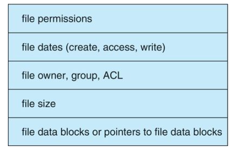
In-Memory Structures
In memory information is used for both file-system management and performance improvement via caching
This is all done in kernel memory
Here, the data is loaded at mount time, and discarded when the drive is dismounted
These structures include:
- In-memory mount table: The in memory mount table contains information about each mounted volume
- In-memory directory-structure cache: Holds the directory information of recently accessed directories(For directories at which volumes are mounted it can contain a pointer to the volume table)
- System-wide open-file table: Contains a copy of the FCB of each open file, as well as other information.
- Per-process open-file table: contains a pointer to the appropriate entry in the system-wide open-file table as well as other information
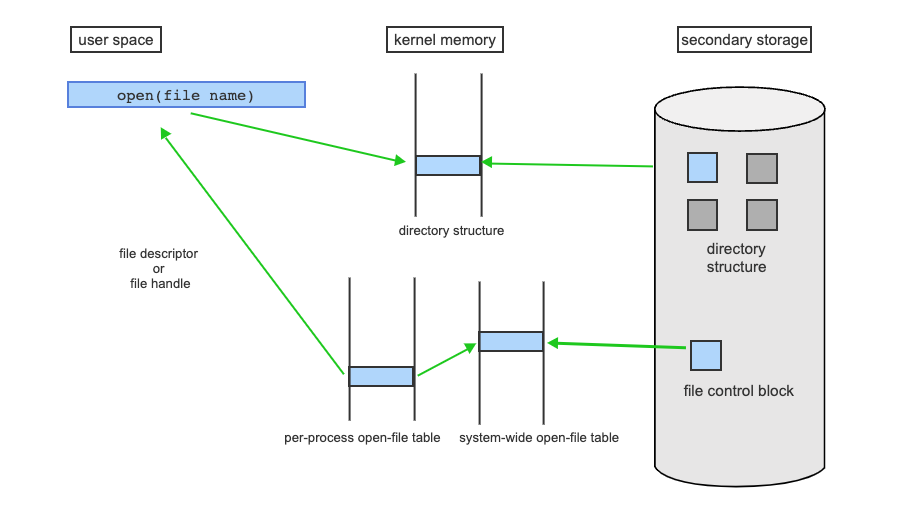
- A process requests open of "file name".
- The directory structure is searched for the given file name.
- The entry is loaded into kernel memory if it's not already in memory.
- The directory structure includes the file control block (fcb) of the file, which is loaded into the system-wide open-file table.
- The per-process open-file table contains pointers to each open file (entry in the system-wide open-file table) that the process can access.
- A file descriptor (on UNIX systems) or file handle (on Windows) is an index into the per-process open-file table that is returned to the calling process to allow it to access the now-open file.
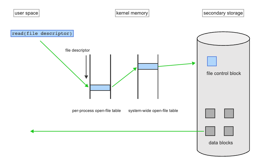
- A read of a data block of an open file uses the file descriptor (or file handle) as an index into the per-process open-file table, which points to the file control block in the system-wide open-file table
- The file control block has the information needed to find the data blocks, and the appropriate data from the data blocks is returned to the calling process
Virtual File Systems
Modern operating systems must concurrently support multiple types of file systems
Object Oriented Techniques
Most operating systems, including UNIX, use object-oriented techniques to simplify, organize, and modularize the implementation of multiple file systems
This allows:
- Very dissimilar file-system types to be implemented within the same structure, including network files systems such as NFS.
- Users to access files that are contained within multiple file systems on the local disk or even on file systems available across the network.
The file-system implementation consists of three major layers:
- Layer 1: The file system interface
- Layer 2: the virtual file system
- Layer 3: the layer implementing the file system type or the remote-file-system protocol
Directory Implementation
The kind of directory allocation and directory-management algorithms used in a system affects the efficiency, performance, and reliability of the file system
The two main methods for implementing a directory are:
- Linear List
- Hash Table
Linear List
This is the simplest method of directory implementation.
Here, a linear list of file names is used which points to the data blocks
This is simple to implement, but time consuming to execute
For Example
To create a new file:
- Search the directory to be sure that no existing file has the same name
- add a new entry at the end of the directory
To delete a file:
- Search the directory for the named file
- release the space allocated to it
The biggest disadvantage of a linear search is that it's always required to find the files. This slows down the entire process as users frequently need to access directory information.
To overcome this, we can use a cache to store information about the files that are recently used, but this is still not very efficient
Hash Table
Here, a linear list stores the entries, but a hash data structure is also used
- The hash table takes a value computed from the file name and returns a pointer to the file name in the linear list
Problems with Hash Table Implementation
- Collisions: situations in which two file names hash to the same location
- Hash tables are generally a fixed size, and the hash functions depend on that size
Contiguous Disk Space Allocation
Contiguous allocation requires that each file occupy a set of contiguous blocks on the disk
Disk addresses define a linear ordering on the disk
Contiguous allocation of a file is defined by the disk address and length of the first block in block units
Example:
If a file is
The directory entry for each file indicates the address of the starting block and the length of the area allocated for this file.
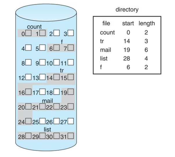
Advantages of Contiguous Space Allocation
Accessing a file that has been allocated is easy
For Sequential Access
- The file system remembers the disk address of the last block referenced
- When necessary, it reads the next block.
For Direct Access
- For accessing block
of a file that starts at block - We can immediately access block
Disadvantages of Contiguous Space Allocation
- finding space for a new file is difficult. First fit and Best fit algorithms can be used for selecting free holes from a set of available holes. However, both these algorithms suffer from external fragmentation
- As files are allocated and deleted, the free disk space is broken into smaller pieces
- Determining how much space is needed for a file is a difficult task.
- if the space allocated for a file is too small, than either the user program must be terminated and more space must be allocated or the system finds a larger hole, copies the content to this new space, then releases the previous space
Linked Disk Space Allocation
The linked disk space allocation method solves all the problems of contiguous allocation.
- Each file is a linked list of disk blocks which may be scattered anywhere on the disk.
- The directory contains a pointer to the first and last blocks of the file.
- Each block contains a pointer to the next block
- For example, if each block is 512 bytes in size, and the disk address(the pointer) requires 4 bytes, then the user sees 508 bytes as usable.
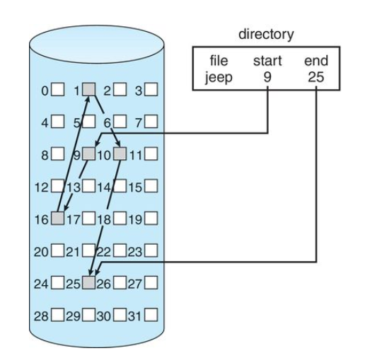
Advantages of Linked Disk Space Allocation
- There is no external fragmentation here (think of this like a page-table style implementation but for storage)
- The size of a file does not need to be declared when the file is created
- Creating, reading, and writing files can be done easily
Creating A File
- Simply create a new entry in the directory
- each directory has a pointer to the first disk block of the file
- the pointer is initialized to nil(the end-of-list pointer value) to signify an empty file
Writing to a file
- find a free block using the free-space management system
- this new block is written to and is linked to the end of the file.
Reading a file
- simply read blocks by following the pointers from block to block
Disadvantages of Linked Disk Space Allocation
- Can be used effectively only for sequential access of files. To find the
block of a file, we must start at the beginning of that file and follow the pointers until we get to the block. - Space required for pointers. If a pointer is required for each block (say 4 bytes out of a 512 byte block) then you are using up storage space. However you can minimize this by allocating pointers to clusters of blocks instead of single blocks, however this could result in internal fragmentation
- Reliability: if pointers used for linking get lost or damaged this will lead to problems
File Allocation Table (FAT)
The file allocation table is a variation of the linked allocation method
- This method is used by MS-DOS and OS/2 operating systems
- A section of disk at the beginning of each volume is set aside to contain a file allocation table
- The table has one entry for each disk block and is indexed by block number
- The directory entry contains the block number of the first block of the file
- The table entry indexed by that block number contains the block number of the next block in the file
- This chain continues until the last block, which has a special end-of-file value as the table entry.
- Unused blocks are indicated by a 0 table value
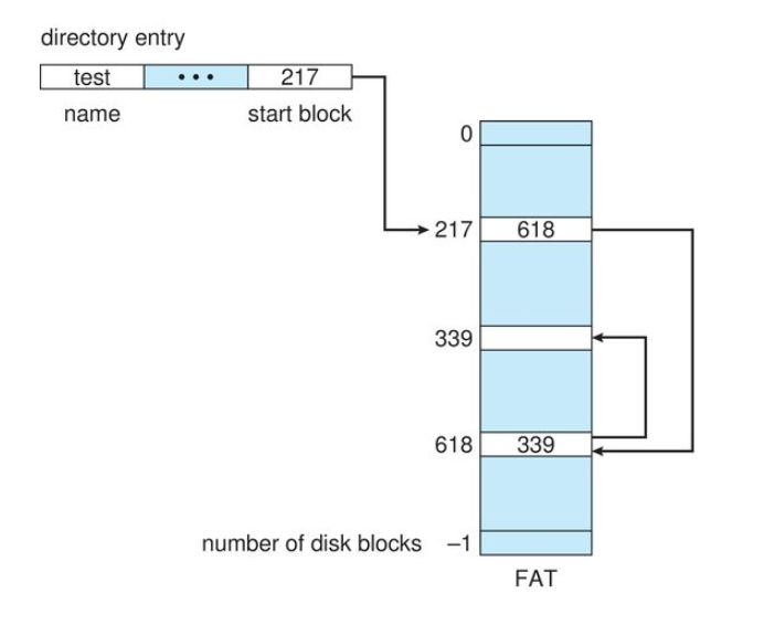
Allocating a new block
- Find the first 0 valued table entry
- Replace the previous end-of-file value with the address of the new block
- replace 0 with the end-of-file value
Advantage of FAT
- random-access time is improved because the disk head can find the location of any block by reading the information in the file allocation table
Indexed Disk Space Allocation
The main disadvantage of linked allocation is that it cannot support efficient direct access. Indexed allocation solves this problem by brining all the pointers together into one location called the index block. This is just a standard disk block that contains all the pointers
- Each file has its own index block which is an array of disk-block addresses
- The
entry in the index block points to the block of the file - The directory contains the address of the index block
- To find and read the
block, we use the pointer in the block entry
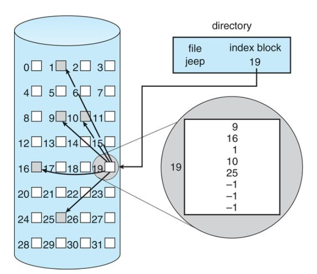
The -1 in the index block denotes pointers that are not in use and they indicate the end of the file.
When Creating A file
- All pointers in the index block are set to nil(-1)
- When the
block is first written, a block is obtained from the free-space manager and it's address is put in the index-block entry
Advantages of Indexed Allocation
- Supports direct access, without suffering from external fragmentation
- Any free block on the disk can satisfy a request for more space
Disadvantages of Indexed Allocation
- It suffers from wasted space. The pointer overhead of the index block is generally greater than the pointer overhead of linked allocation
How large should index blocks be?
- If it is too small, it will not be able to hold enough pointers for a large file.
- If it's too large it is wasted space
We can deal with this by in a couple of ways:
- A linked Scheme: You can have multiple index blocks that are linked to each other
- A multilevel index: A variant of linked representation uses a first-level index block to point to a set of second-level index blocks, which in turn point to the file blocks. To access a block, the operating system uses the first-level index to find a second-level index block and then uses that block to find the desired data block. This approach could be continued to a third or fourth level, depending on the desired maximum file size. With 4,096-byte blocks, we could store 1,024 four-byte pointers in an index block. Two levels of indexes allow 1,048,576 data blocks and a file size of up to 4 GB.
- A combined scheme: An index block is created and the first few entries point directly to the disk blocks, then the last few entries will point to index blocks
The Unix Inode
This is a modified indexed allocation method
An inode is a data structure in UIX operating systems that contains important information pertaining to files within a file system
- When a file system is created in UNIX, a specific amount of inodes are also created
- Usually, about 1% of the total file system disk space is allocated to the inode table
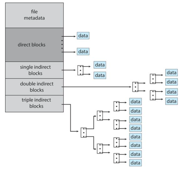
- Metadata: contains information like mode, owners, timestamps, size block, and count
- Direct Blocks: These contain the pointers or the address to the blocks directly - usually around 10 to 12 blocks
- Single Indirect Blocks: There is just one pointer or address that points to an index block which will contain the pointers to the disk blocks
- Double Indirect Blocks: This points to the address of an index block which contains pointers(addresses) of other index blocks which point to the data
- Triple Indirect Blocks: Contains a three level index block scheme.
This is good for maintaining large files and small files alike.
Performance of Disk Space Allocation
We have seen 3 main types of allocation methods:
- Contiguous Allocation
- Linked Allocation
- Indexed Allocation
These methods vary in storage efficiency and data-block access times. These are important criteria in selecting a method for an operating system to implement
Contiguous Allocation
Requires only one access to get a disk block for any type of access(sequential or direct). Only the initial block address has to be kept in memory.
This is good for:
- Sequential Access
- Direct Access
Linked Allocation
The address of the next block can be kept in memory and can be read directly. Therefore, it's really good for sequential access, but an access to the
This is good for:
- Sequential Access
Some systems make use of both contiguous and linked allocation methods. For files that require direct-access they use contiguous allocation, and for files that make use of sequential access they use linked allocation
This must be declared when the file is created.
Indexed Allocation
This is good for:
- Sequential Access
- Direct Access
Performance in this system depends on:
- Index Structure
- Size of the file
- Position of the desired block to be read
Some systems combine contiguous allocation with indexed allocation. For small files they use contiguous allocation. If the file grows large, it is switched to an indexed allocation method.
Free-Space Management
We know that disk space is limited, so we need to reuse the space from deleted files for new files if possible.
To keep track of free disk space, the system maintains a free-space list which records all free disk blocks, those not allocated to some file or directory
To Create A File
- We search the free-space list for the required amount of space
- We then allocate that space to the new file
- Then this space is removed from the free space list
When A File Is Deleted
- Its disk space is added to the free-space list
The Free Space List
There are a few ways we can implement a free space list:
- Bit Vector
Bit Vector
The free-space list is implemented as a bit map or bit vector
- Each block is represented by 1 bit
- If the block is free, it is represented as a
1and if the block is occupied it is set to0.
Consider a disk where blocks 2,3,4,5,8,9, 10, 11, 12, 13, 17, 18, 25, 26, and 27 are free and the rest of the blocks are allocated. The free-space bitmap would be:
001111001111110001100000011100000 ...
Advantage
It is relatively simple in finding the first free block or n consecutive free blocks on the disk
Disadvantage
It's inefficient unless the entire vector is kept in main memory
Linked List Method
All the free disk blocks are linked together
- A pointer pointing to the first free block is kept in a special location on the disk.
- It is cached in memory
- This first block contains a pointer to the next free disk block and so on
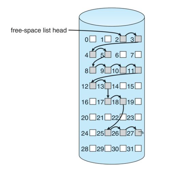
Grouping Method
Here we store the addresses of
- The first
blocks are actually free - The last block contains the addresses of another
free blocks and so on. - the addresses of large number of free blocks can now be found quickly, unlike the situation when the standard linked-list approach is used.
Counting Method
The counting method takes advantage of the fact taht generally, several contiguous blocks may be allocated or freed simultaneously, particularly when space is allocated with the contiguous allocation algorithm or through clustering.
- we keep the address of the first free block and the number
of free contiguous blocks that follow the first block. - Each entry in the free-space list then consists of a disk address and a count.