Zephyr RTOS
Device Tree
Zephyr Device Tree Mysteries, Solved.
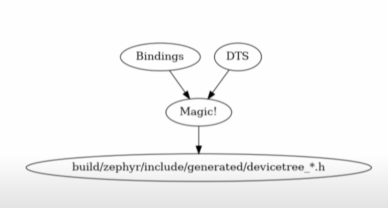
The device tree is parsed at compile time and converted in to C header files
All device tree info is accessible at compile time via the zepher/devicetree api
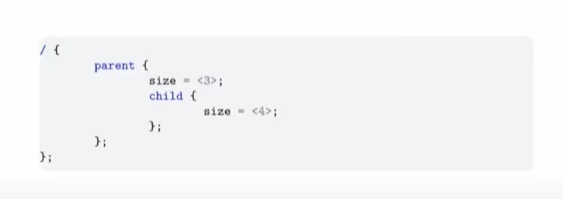
How zephyr.dts gets converted to devicetree_unfixed.h
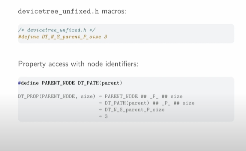
Macrobatics is the solution to having quotes in fields
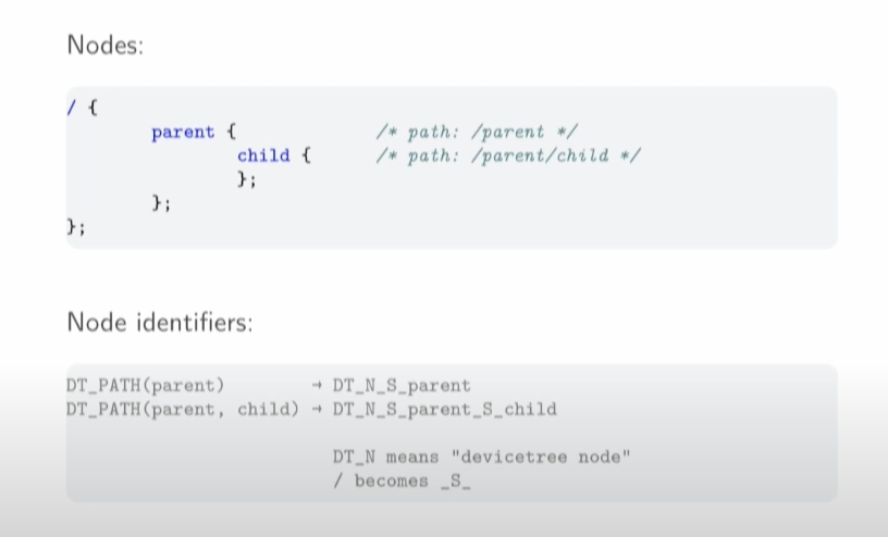
DT_N = devicetree node
Anytime there is a slash, it's replaced with a capital S
DT_N_S_parent_S_child would be /parent/child
so DT_N_S_foo_S_bar would be /foo/bar
These ARE NOT VALUES they are just tokens
But...we can use them to get the value without any over the overhead that we're trying to avoid
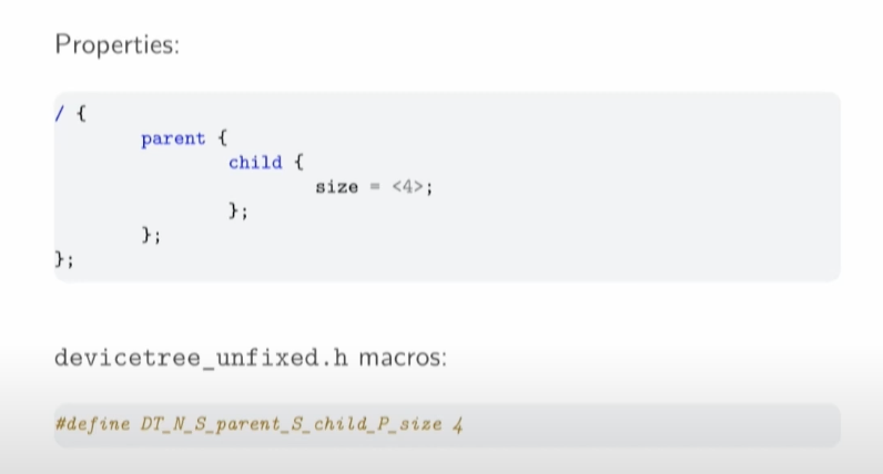
Capital P is property, followed by the name of the property, in this case, "size "
This is why we lowercase and underscore
Device Tree Bindings
Device tree bindings are basically schema for nodes and is a description of what the node may contain. Necessary to preform the conversion to C
Important Device Tree Properties
- Compatible: the name of the hardware a node represents, typically vendor, device. Used to find the bindings for a node.
- Label: Name of the device(unique)
- reg Information used to address the device (optional) value meaning depends on the device. In general, a sequence of address-length pairs.
- status: status of the device (ok or disabled)
You can have multiple instances of a device and each can have its own properties
Pin Control
Deep Dive into Pin Control In Zephyr
Pin control covers 2 things, basic pin multiplexing (ie: UART to pin 27) or pin configuration parameters needed to make a device work.
Pin Control is NON-PORTABLE
The main purpose of pin control is to perform both signal multiplexing and pin configuration required for the operation of the peripheral
GPIO drivers are for GENERAL purpose control of a pin, ie when logic level is read or controlled manually.
usually GPIO can be seen as a subset of pin control
State Model
Some device drivers need a certain pin configuration to be applied to work correctly
Pin configuration requirements may change at runtime
Each required pin configuration is modeled as a state
States encode all necessary pin configurations and are independent of each other
States isolate driver code from a configuration
Standard States
In general, Pin Control States can have arbitrary names
A naming convention has been established for the most common use cases
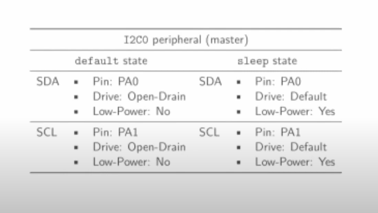
State: Default, Identifier: PINCTRL_STATE_DEFAULT - operation state
State: Sleep, Identifier: PINCTRL_STATE_SLEEP - low power or sleep modes
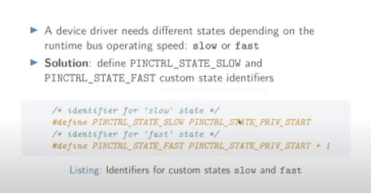
Some device drivers may require custom states. This can be done by naming using PINCTRL_STATE_{NAME} where {NAME} is the capitalized state name
Custom state identifiers are in both driver's scope and start from PINCTRL_STATE_PRIV_START
You can SKIP using PINCTRL_SKIP_
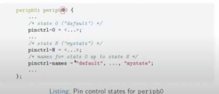
Each device's pin control state is represented in Devicetree by pinctrl-N properties where N is the state index starting from zero
pinctrl-names property is then used to assign the state to each property by index
Pin Configuration
- There are multiple ways to represent pin configurations in device treee
- All representations encode the same information: The pin multiplexing and the pin configuration parameters
- Representation choice depends largely on vendor preferences
- A couple of popular choices: grouping and node-based
- Standardized properties are mandatory. For example, bias-pull-up has to be used to activate a pin pull-up resistor. They are pre-defined in pincfg-node-group.yaml or pincfg-node.yaml