CSS 427 - Introduction to Embedded Systems
We will cover
- components
- Electronics and hardware chips/devices
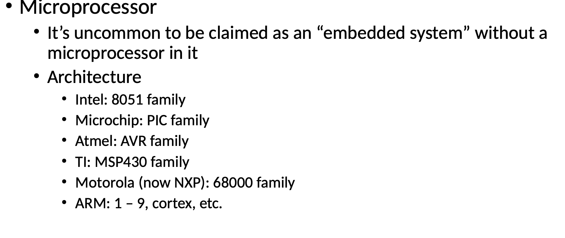
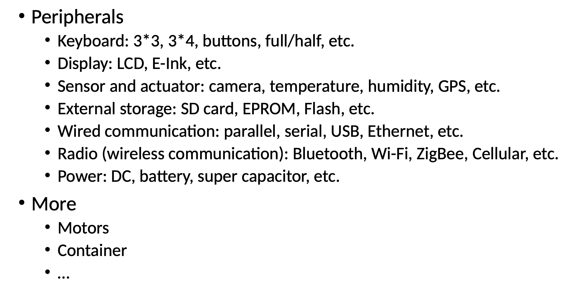
- Microprocessor: internals and periferals
- Communications: within and between embedded systems
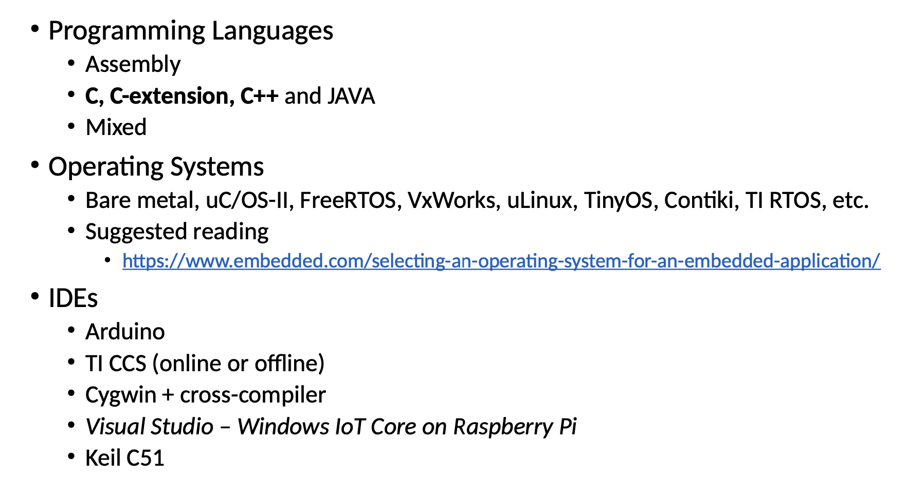
- Software: embedded system progremming principles
- System
- an individual embedded system
- networked embedded systems
- Advanced
- Real-Time Operating Systems - RTOS
- Industry Standards/Protocols or your proposed topics

Which of the following is an embedded system?
- Smartphone
- Fitbit
- Router
- Vending Machine
- Calculator
- TV Remote
Hardware Overview
C Vs Arduino
The language is an extension of C
- Arduino based on AVR Architecture
- Arduino IDE - newly created wheel
- based on processing
- Arduino Programming Language - not new
- Based on Wiring
Try to follow C style
- Based on Wiring
Look into attachInterrupt() and detachInterrupt
Lecture 2
Hardware Fundamentals
Key Terms
| Term | Description |
|---|---|
| Pin | Port |
| DIP | Dual Inline Package |
| PCB | Printed Circuit Board |
| VCC | Voltage Connected To Controller |
| Ground | GND |
| Asserted Signal | Signal Selection |
| PLCC | Plastic Laded Chip Carrier |
| TSOP | Thin Small Outline Package |
| PQFP | Plastic Quad Flat Pack |
| MCU | Micro Controller Unit |
Pull Up Resistor
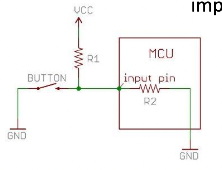
The general rule is to use a pull up resistor that is an order of magnitude (1/10) of the input impedance of the input pin.
The purpose is to provide a clean logic level.
Timing
There may be a delay (propagation delay) while a signal passes through a gate
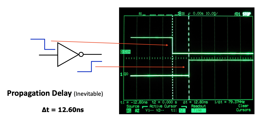
Rising Edges - the transition of a signal from low to high
Falling Edge - the transition of a signal from high to low
This is important for interacting with flip flops
Clocks
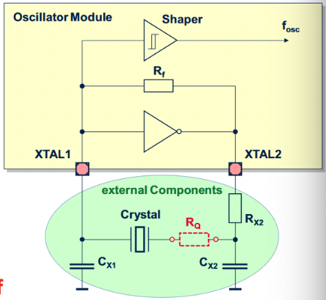
Oscillators: generates a clock signal by itself
- uses 4 pins: GND, VCC, soldering point, clock signal out
Crystal: must build a circuit to get a clock signal out
- two pins (many circuits containing the two pins to be connected to a crystal)
Selecting a Crystal
Have the clock signal frequency be an integer multiple of the data rate on your communication mediums (serial port, network port, etc)
Power
Input Power
| Term | Info |
|---|---|
| Power Source | AC, Batter, Solar, Vibration, Etc |
| Converter | AC-DC, DC-DC, step-up, step-down |
| Regulator | regulate the voltage to a working level for a processor |
| Decoupling Capacitor | A capacitor than can smooth over brownouts |
Output Power
- drive up peripheral circuits
- voltage
- current
- duration
Memory
| Type | Name | Description |
|---|---|---|
| PER | Program, Erase, Read | Industry Term: PER Cycle, To evaluate the lifetime of a memory device |
| ROM | Read-Only Memory | |
| PROM | Programmable ROM | |
| EPROM | Erasable Programmable ROM | |
| EEPROM | Electrically Erasable ROM | |
| RAM | Random Access Memory | |
| Volatile RAM | SRAM/DRAM | |
| Non-Volatile RAM | Flash, FRA< |
ROM
- Not writable by users (can be overwritten limited times)
- Data is persistent (non-volatile) after power-off
- Fast Read: like microprocessor's speed of executing instructions
- Typically used to save program instructions (code)
- Can be used to store settings/information
PROM (Programmable Read-Only Memory)
- Blank from manufacture
- Can be programmed with a PROM Programmer (burner)
- Only write once
- Fast to program (seconds)
- Burn another one if you made a mistake
- Why do we need it?
EPROM (Erasable Programmable Read Only Memory)
- Similar to PROM but can be reprogrammed
- Erased first, then programmed
- Reads Fast
- Shining a strong UV light into a window of the chip to erase
- Erases slowly (10-30 min)
EEPROM (Erasable Programmable Read Only Memory)
- EEROM = EEPROM
- Slow Read
- Slow Write
- Store Limited Data
- Limited Lifetime (in millions)
- Typically used to store configuration data
Flash
- Similar to EEPROM
- Fast Read
- slow write
- Limited Lifetime (similar to EEPROM)
- not for frequently changed data
- good for storing programs (adopted into embedded systems now)
- NAND Flash Operation Unit is a "block" or "page" but not a byte (more common)
- NOR Flash byte level operation
| Technology | Read Speed | Write Speed | Write Times | Volatile | Application |
|---|---|---|---|---|---|
| Rom | Fast | N/A | 0 | No | Storing Programs |
| PROM | No | ||||
| EPROM | No | ||||
| EEPROM | No | ||||
| NAND FLASH | Fast | Slow | Limited | No | |
| NOR FLASH | No | ||||
Random Access Memory
-
Fast Read and Write
-
Typically used to store Data
-
Infinite Write Times
-
Lost Data After Power-off (non-volatile)
- RAM retention power
-
Static RAM: remember data without assistance from other circuits
- Expensive
-
Dynamic RAM: Need to be read periodically to keep data
- cheap
DRAM (Dynamic RAM)
- Designed based on transistor and capacitor
- 1: Capacitor is charged
- 0: Capacitor is discharged
- Data may be lost if capacitor is self-discharged(leaked)
- Need to recharge the capacitor periodically(refresh)
- Feature
- High Density
- Cheap
- Relatively High Power Consumption
- Usage
- RAM in your computer, XBOX, and other consumer products
- Embedded DRAM (eDRAM)
- DRAM integrated on the same die or multi-chip module of an ASIC or MCU
SRAM
- Designed based on transistors only
- No capacitor, no data leak, no refresh
- Features (compared to DRAM)
- Expensive
- Low Density
- Low Power Consumption
- Usage
- Processor Cache
- Store Register Value in some microprocessors
- integrated into many microprocessors
- check the processors data sheet
Combination of RAM and ROM
- RAM - Volatile
- ROM - Non-Volatile
- persistent data after power off
- yes, we want it
- Fast read/write/erase speed -> Yes we want it
- Long lifetime, unlimited PER Cycles -> Yes we want it
- Large Capacity and Low Price -> Yes we want it
Non-Volatile SRAM (nvSRAM)
- Combines SRAM cells with EEPROM cells
- adding EEPROM to the SRAM chip
- Operation
- Read and write to SRAM at higher speeds
- Data in SRAM is then stored or retrieved from EEPROM at lower speed
- Auto store at power down using the charge from an external capacitor
- Auto retriev at power up
- Unlimited PER cycle
- Mostly no battery
Ferroelectric RAM(FRAM)
-
Read/write by byte
-
Fast read and write
-
Non-Volatile
-
Relatively expensive
-
Relatively low power usage
-
much improved lifetime (10-20 years) but not infinite
-
Lower storage densities
-
Some TI microprocessors integrate this type of FRAM
- many TI MSP430 microcontrollers have integrated small amount of FRAM
-
Other manufactures can produce individual FRAM chips
- Fujnitsu, Cypress Semiconductor
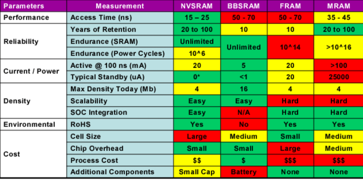
Ram Comparrison
| Technology | Read Speed | Write Speed | Write Times | Volatile | Applications |
|---|---|---|---|---|---|
| SRAM | |||||
| DRAM | |||||
| FRAM | |||||
| nvSRAM |
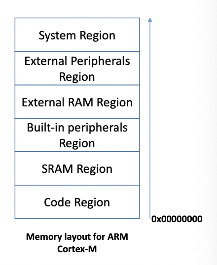
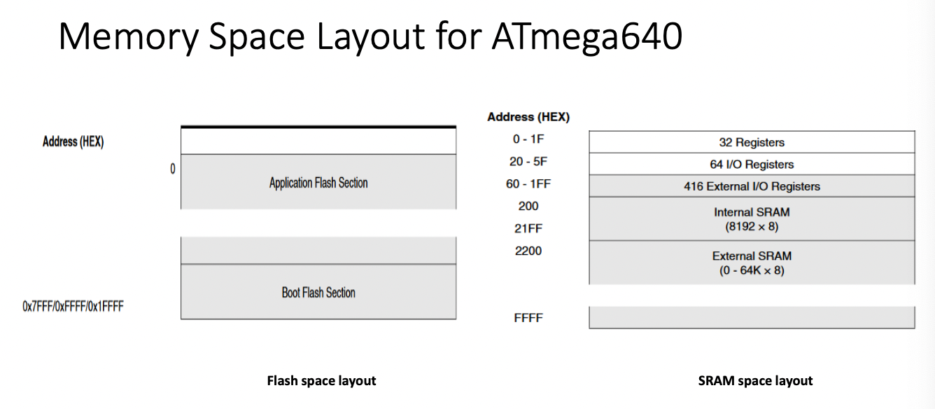
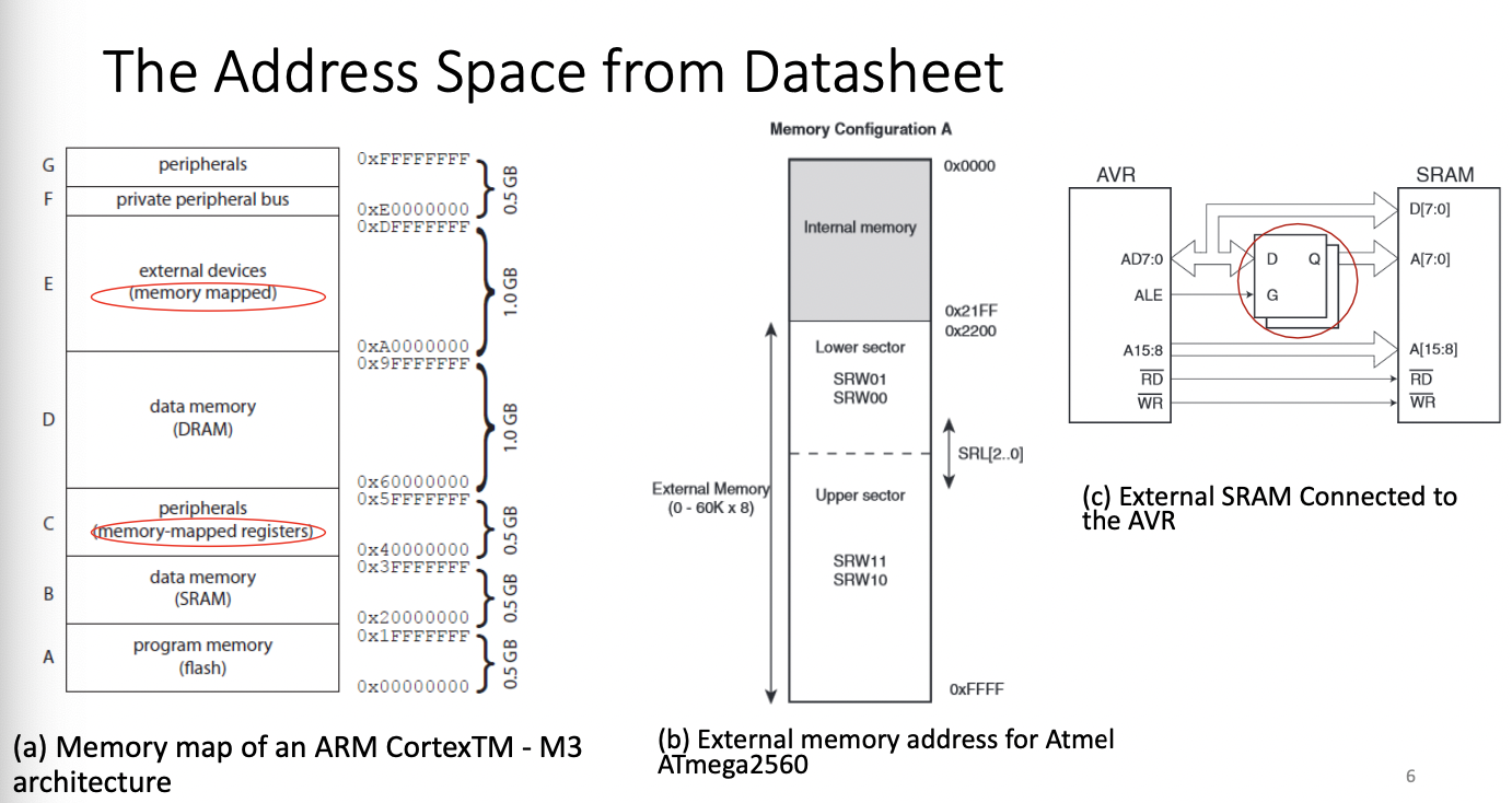
Memory Model and Address Space
- Fully Mapped Memory Address
- Flash Memory
- Lower Space, executable address space
- Internal Ram
- Next to flash, non-executable
- Peripherals Internal to the Microcontroller
- E.G. DMA, ADC
- External Ram
- External Peripheral Bus
- System Control registers
- Accessible in privileged level
- Accessible in privileged level
- Flash Memory
Memory Space Layout for ATmega640
From Code To Memory
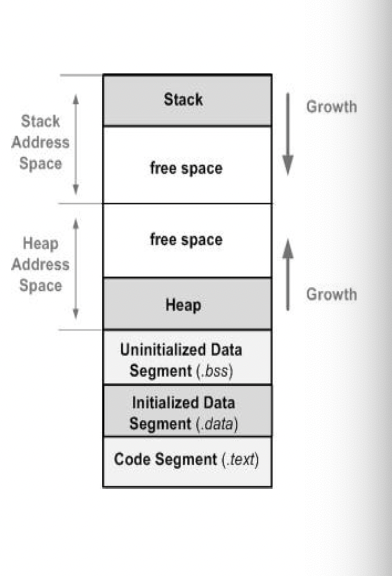
- Segment
- Code (.text) stores only code
- Data (.data) stores initialized data
- BSS (.bss) stores uninitialized global and static variables (initialized to 0) (Block Starting Symbol)
- Heap: for sata storing on dynamically allocated memory
- Stack: for local variables
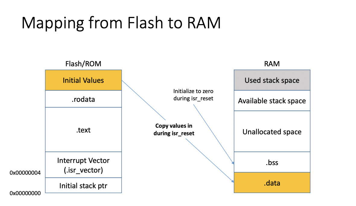
- Code (.text)
- ROM, mostly in flash now
- Data (.data, .bss, heap, stack)
- Initialized global and static data: takes ROM/Flash space, copied to RAM
after startup (will occupy both ROM and RAM space) - Uninitialized global and static data: only takes space in RAM
- Dynamic Allocated Data (heap) RAM
- Local variables (stack) RAM
- Const Data
- saved in .rodata segment(read only segment)
- occupy the ROM space in most cases
- Initialized global and static data: takes ROM/Flash space, copied to RAM
- For this class, CONST data will be stored on ROM
&= clear
|= set
| Technology | Read Speed | Write Speed | Write Times | Volatile | Application Example | ||||||
|---|---|---|---|---|---|---|---|---|---|---|---|
| ROM | Fast | Non-Writable | 0 | No | Storing Program Instruction | ||||||
| PROM | Fast | Can Only Be Written Once | 1 | No | Storing Program Instructions | ||||||
| EPROM | Fast | Slow | 100-10000 | No | Storing Program Instructions | ||||||
| EEPROM | Slow | Slow | Limited, millions | No | Configuration Data | ||||||
| NAND Flash | Fast | Slow | Limited, similar to EEPROM | No | Storing programs | ||||||
| NOR Flash | Fast | Slow | Limited, Similar To EEPROM | No | Storing Programs | ||||||
| SRAM | Fast | Fast | Infinite | Yes | Processor Cache, Register Values | ||||||
| DRAM | Fast | Fast | Infinite | Yes | RAM for stack/heap usage (similar to computer Usage) | ||||||
| FRAM | Fast | Fast | 10-20 year lifetime | No | Any place you want fast write and non-volatile memory, for example, a data logger in an application that may lose power |
Lecture 3
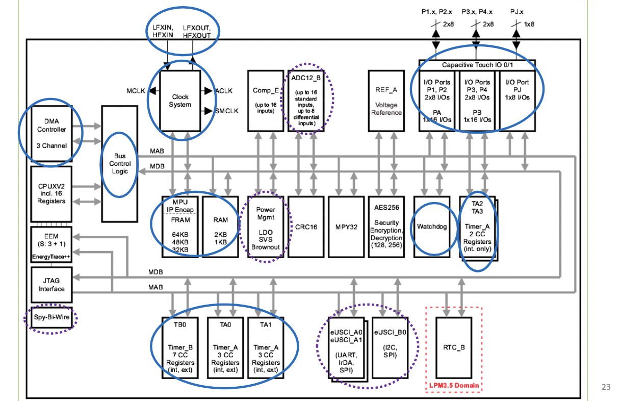
Microprocessor Internals
Busses
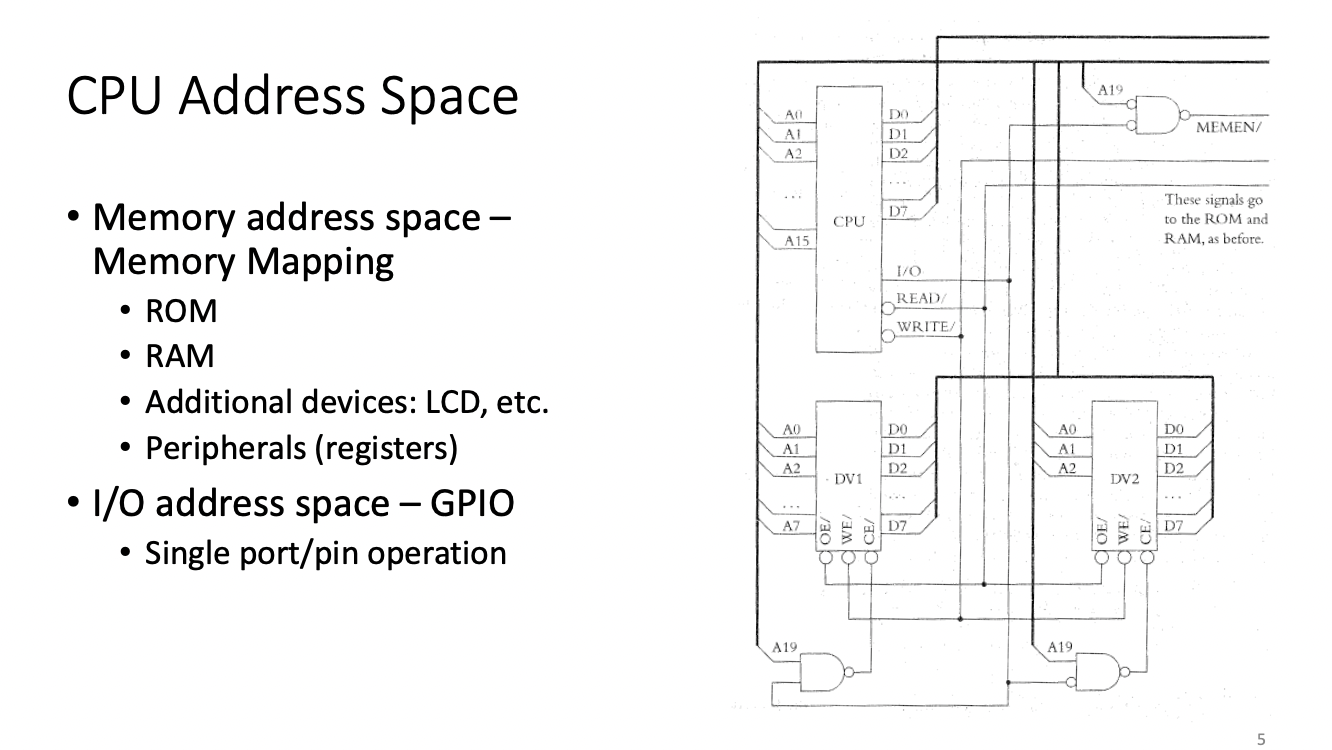
Each register is mapped to an address
To use a register, it must be connected to the bus
Almost every component inside an MCU can be exchanged to an external
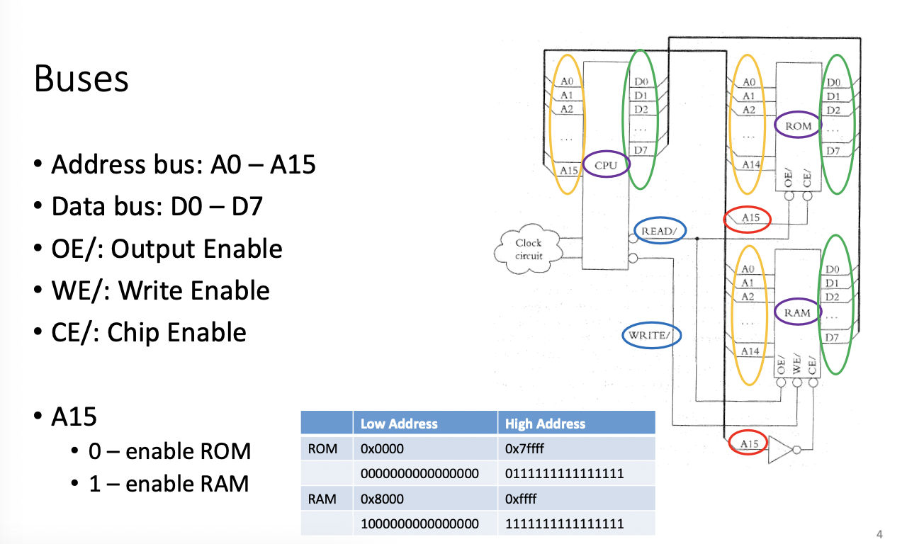
A bubble on the input means enabled low
When A15 is low, Rom is selected, when A15 is high, RAM is selected
When looking at the address, look at MSB
Every component in a system is mapped to read or write
Thick lines represent busses, the higher the number, the higher the address
Address Bus A0-A15
Data Bus D0-D7
You may also have a controll bus (Read Selection/Write Selection)
OE = Output Enable
WE = Write Enable
CE = Chip Enable
We talk about the bus system so we can talk about interrupts
There may be bus contention since each component needs to use the bus 1 by 1
Bus Handshaking
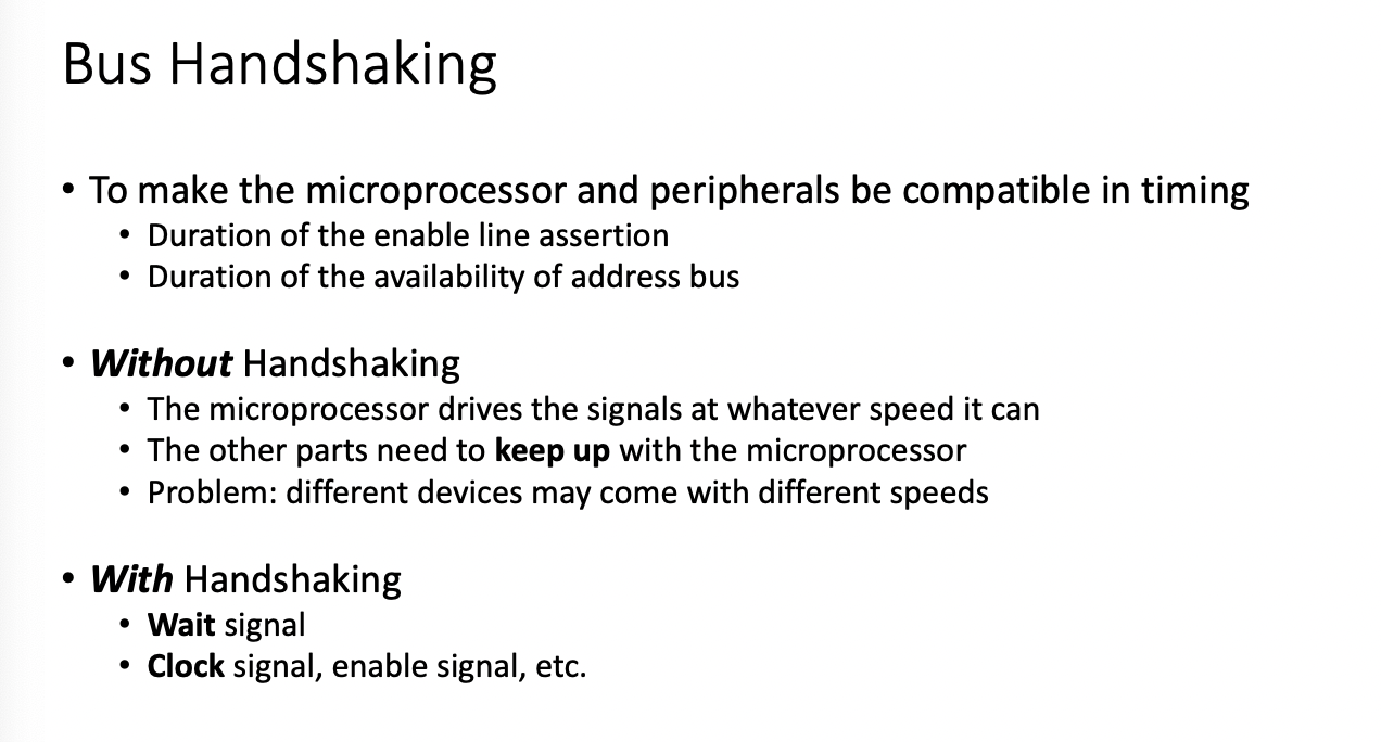
Used to synchronize everything.
Without handshaking the microprocessor just executes as fast as possible...peripherals may not be able to keep up with the microprocessor, different devices may come with different speeds
With handshaking-
wait signal, clock signal, enable signal etc
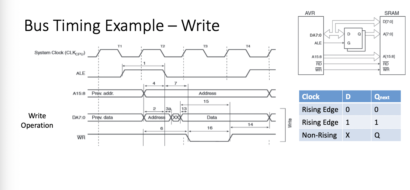
ALE = Adress Enable Latch
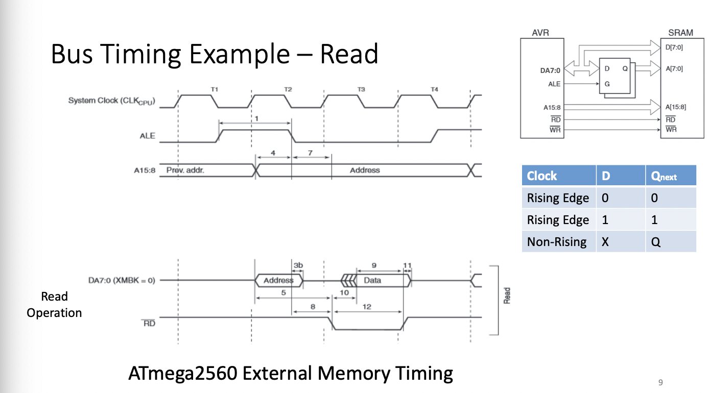
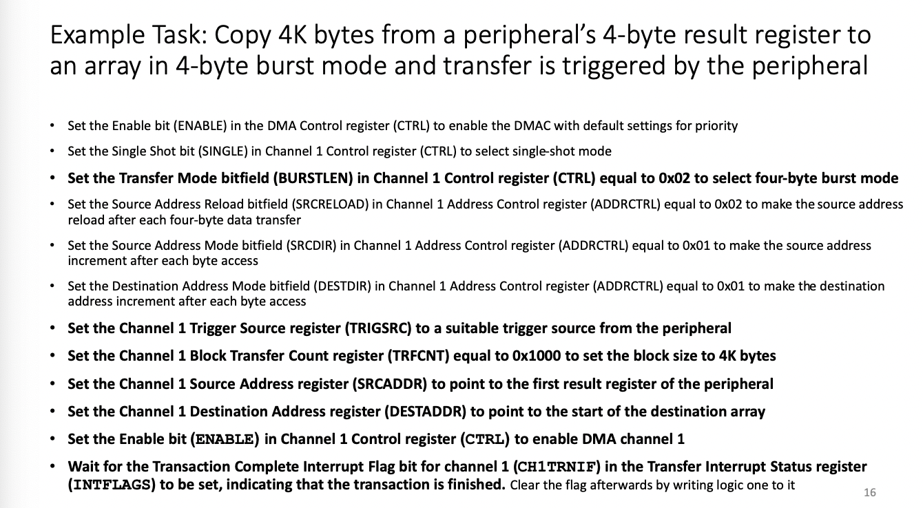
DMA: Direct Memory Access (SRAM)
Typically provided to you as a component
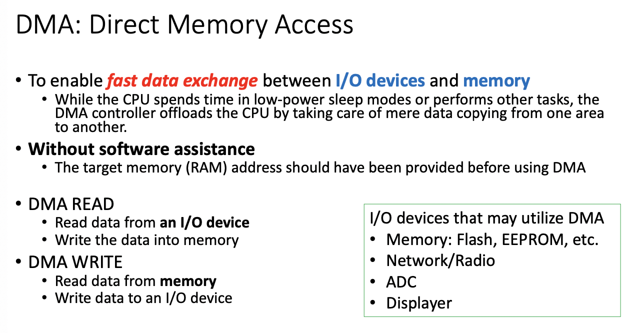
You can think about DMA as a memory delegator which can free the CPU from operations.
Anytime we want to read from a peripheral to RAM we can use DMA, however, we have limited DMA channels
While the DMA is working, the CPU cannot access the Data Bus or Address Bus
The device makes a request to the DMA, the DMA makes a request to the Bus, the Bus acknowledges, the DMA acknowledges, then the Address bus reads/writes then the Data Bus can transfer info.
Direct Memory Access - Fast Data Exchange between I/O Devices and Memory
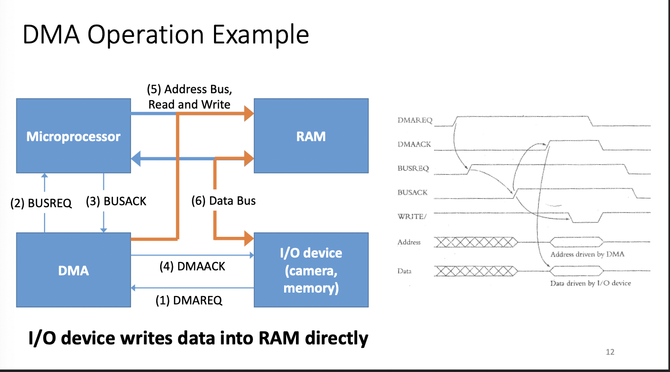
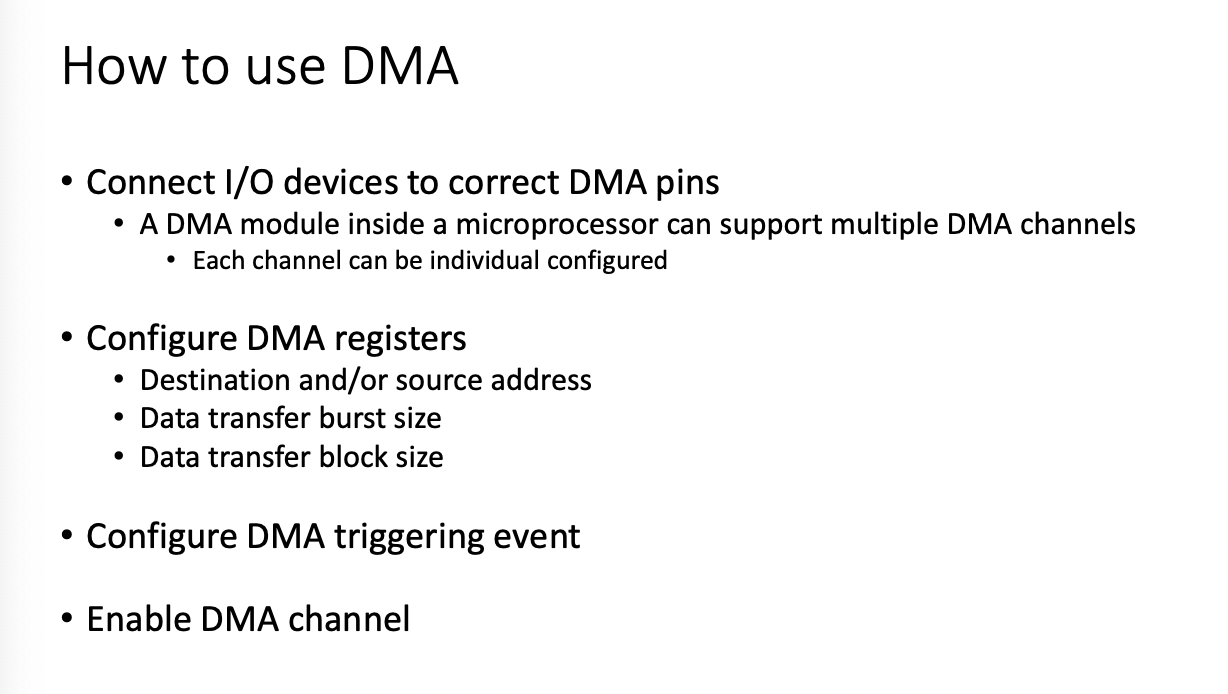
Below is just a summary of the most important operations
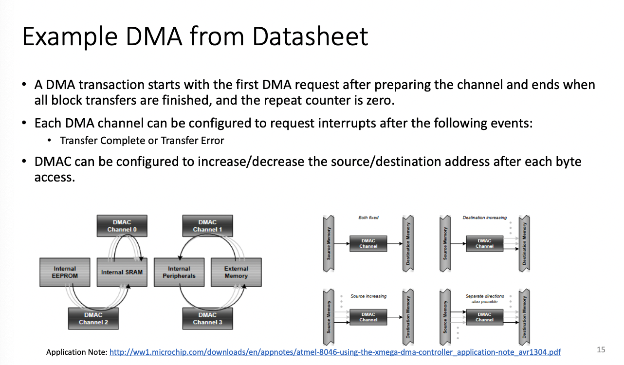
DMA READ
- read data from an I/O device
- Write data into memory
DMA WRITE
- Read Data from Memory
- Write Data to an I/O device
DMAC = DMA Controller
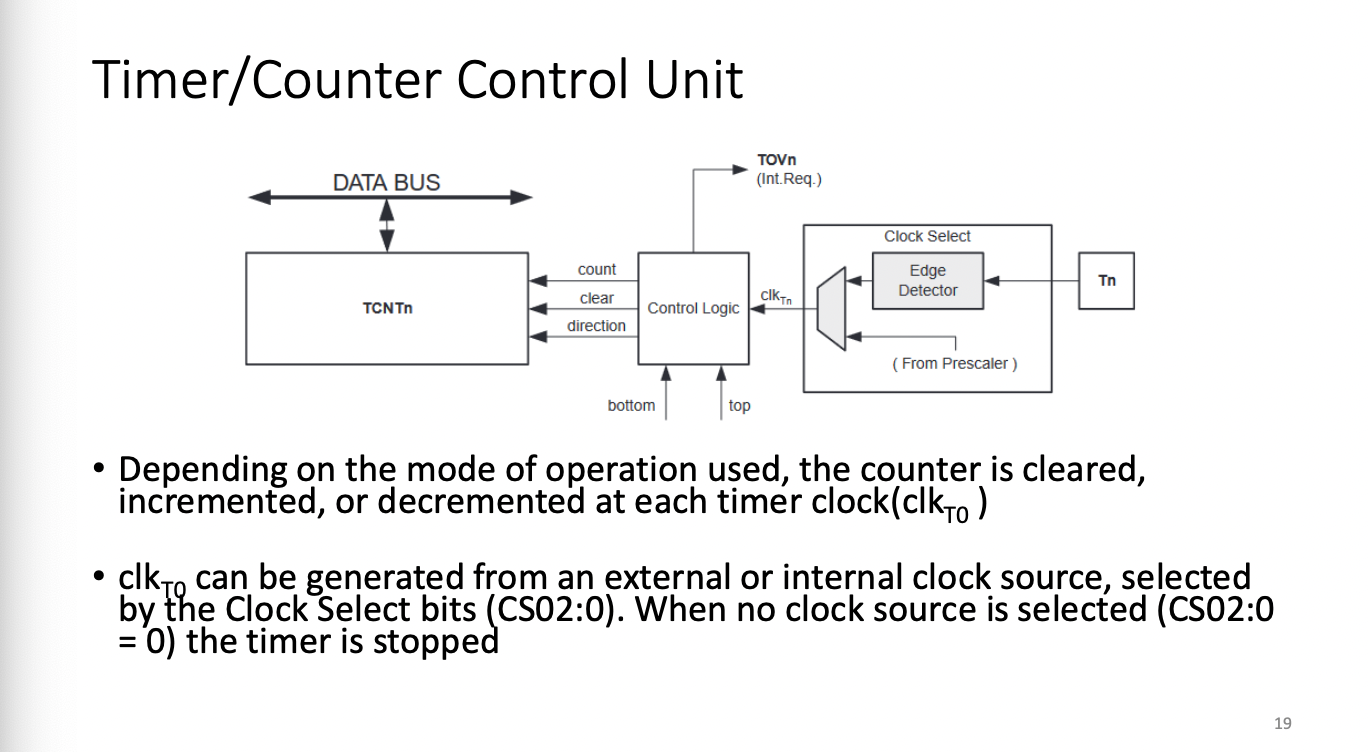
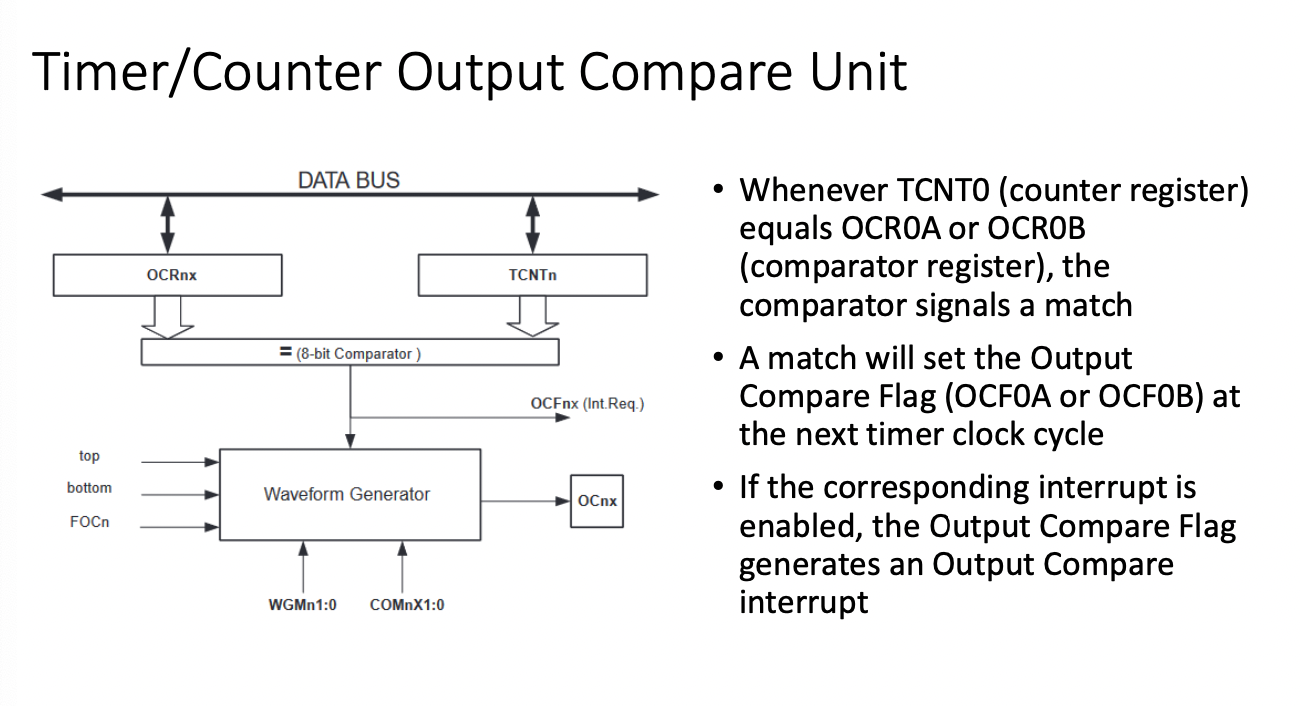
Clocks
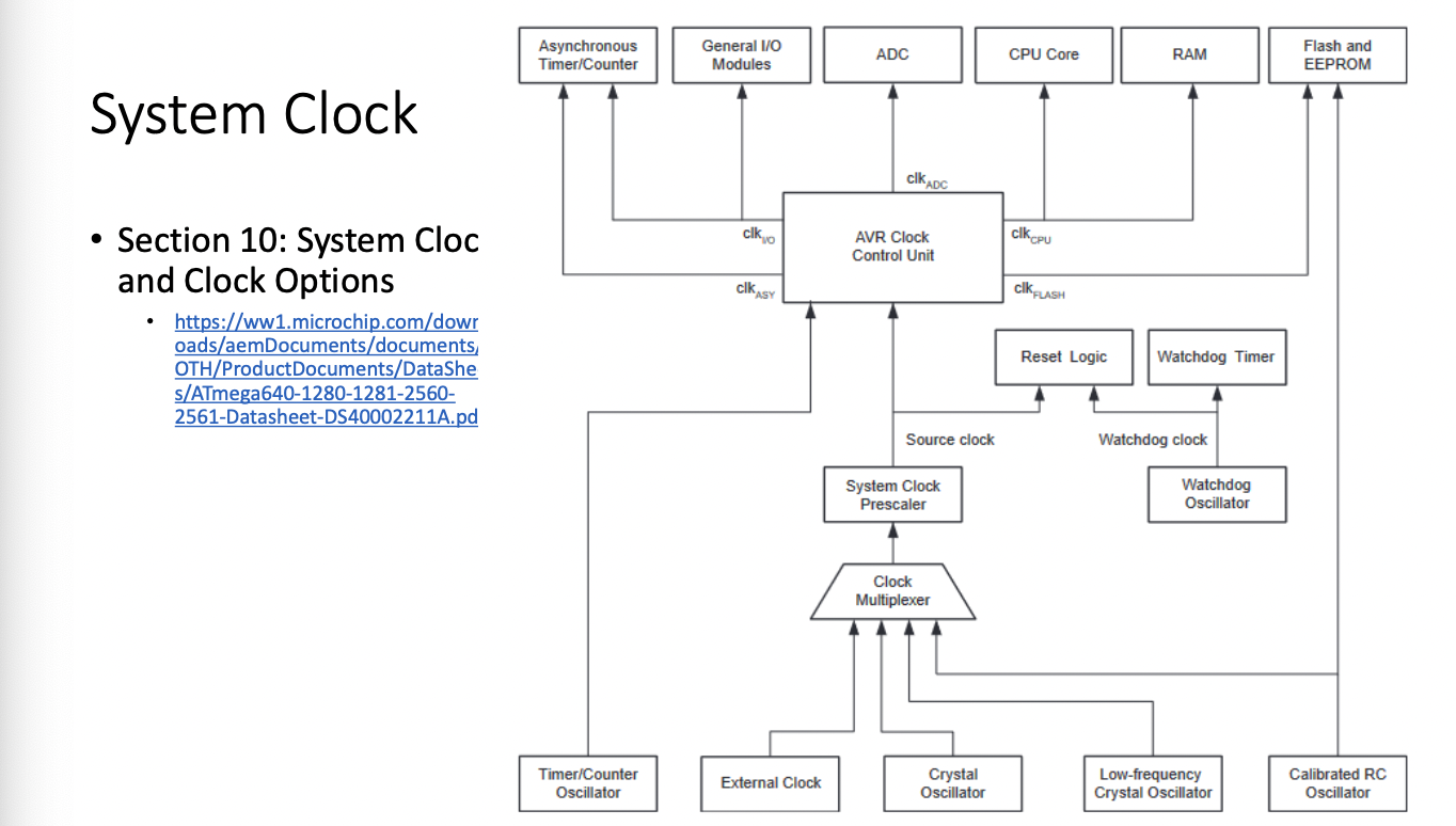
This system has multiple clock signals...the EEPROM has designated Oscillator
Pre-scaler scales a clock that may be too high. You can only slow down a clock signal, you can't increase a clock
Different counters may have different "bits". for example, an 8bit timer may go from 0-255, or 16bit could go from 0 to 65535
Different timers may give you different "resolution"
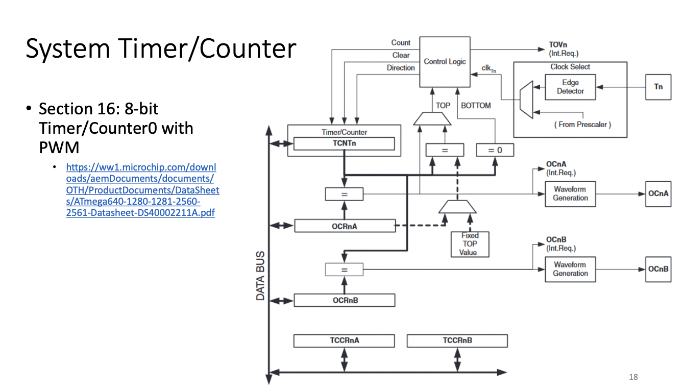
TCNTn timer register
OCRnA = value register....when TCNT = OCRnA - timer out
TCCR Timer Counter Control Register
Watchdog
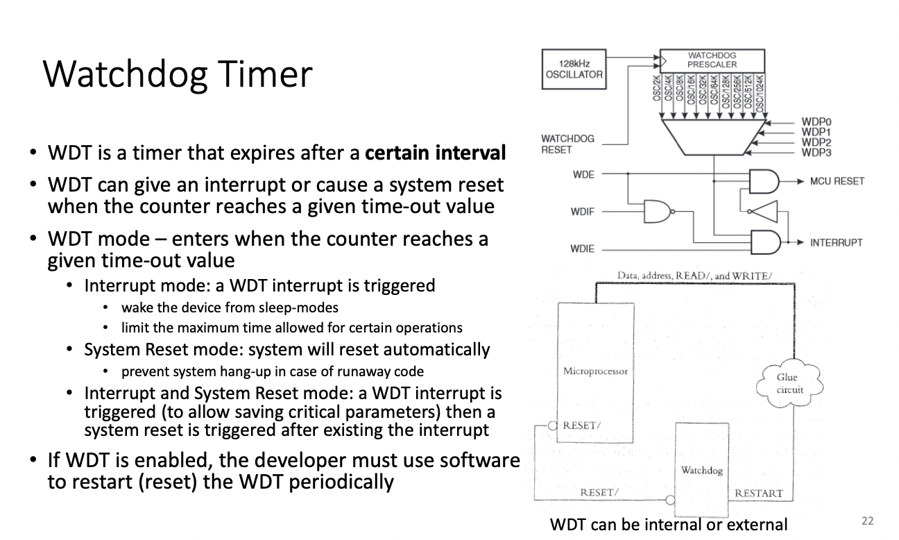
A watchdog can reboot in cases such as infinite loops
If you use a watchdog, it won't be cleared automatically, you need to clear it manually.
Sensors
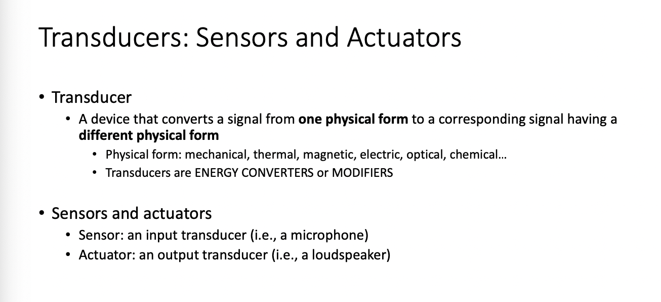
Transducer - converts one physical form to a different physical form
Sensor an input transducer
Actuator an output transducer
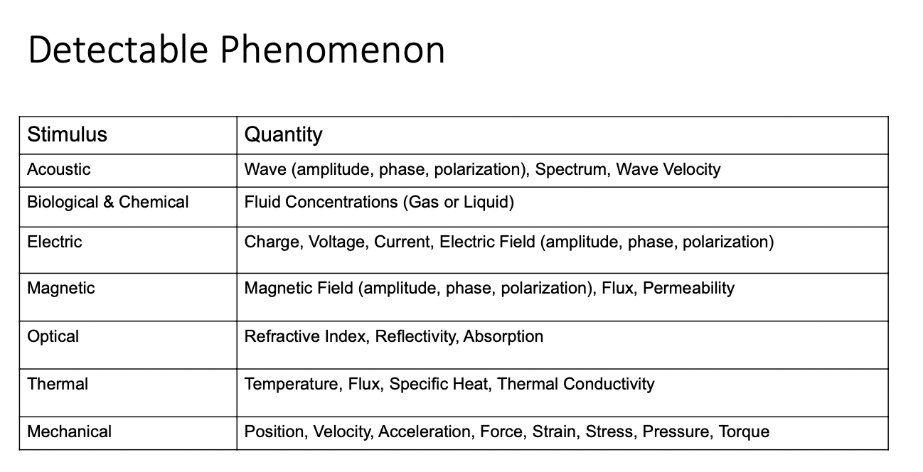
Sensor - a device which provides a usable output in response to a specified measurand - it requires a physical paramter and converts it to a signal for processinggo
Lecture 4
Sensors and ADC
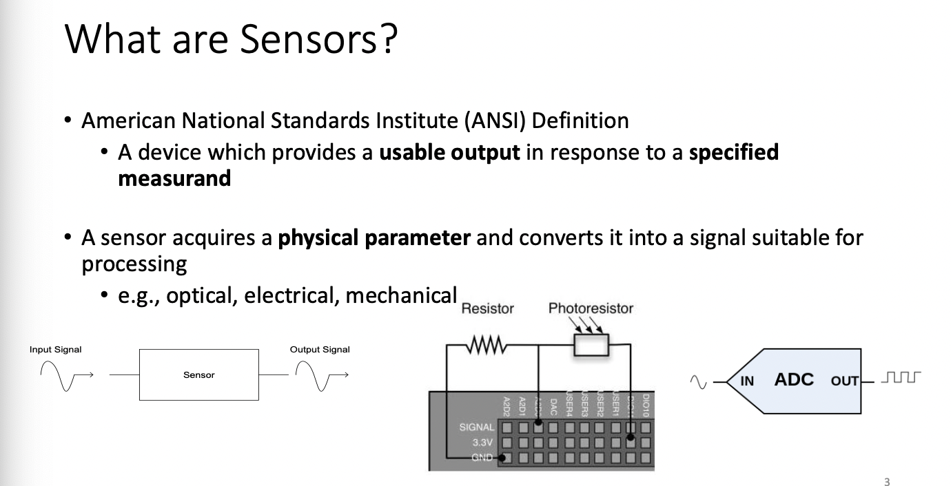
ADC
ADC Takes sinusoidal input, and gives a digital output
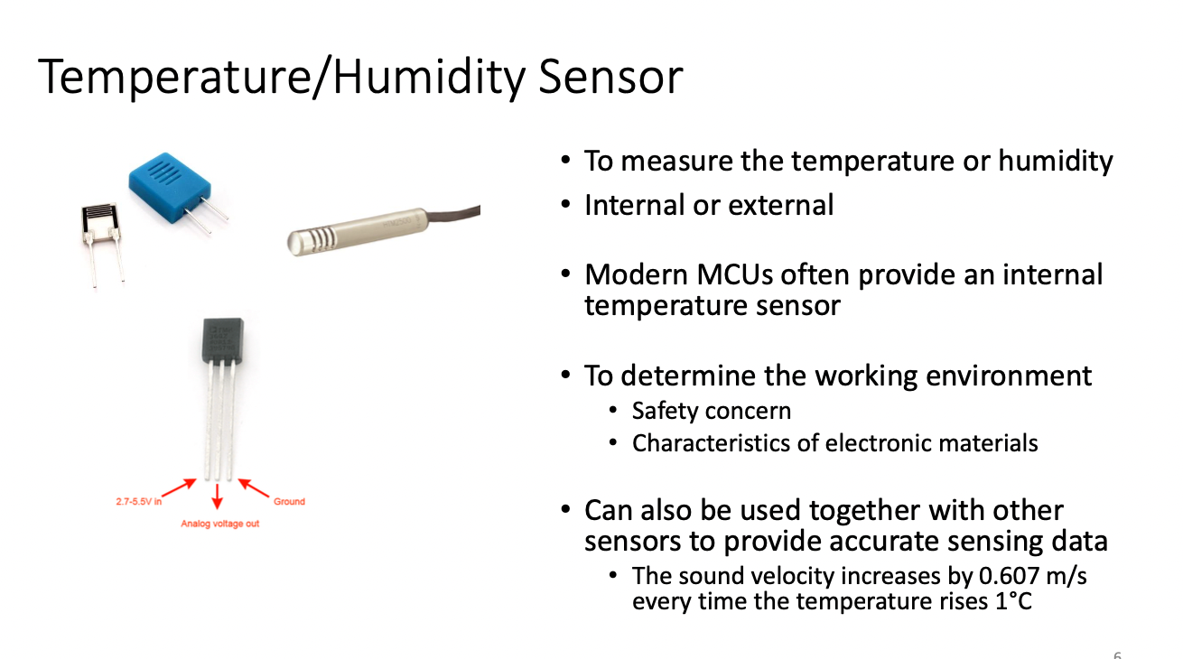
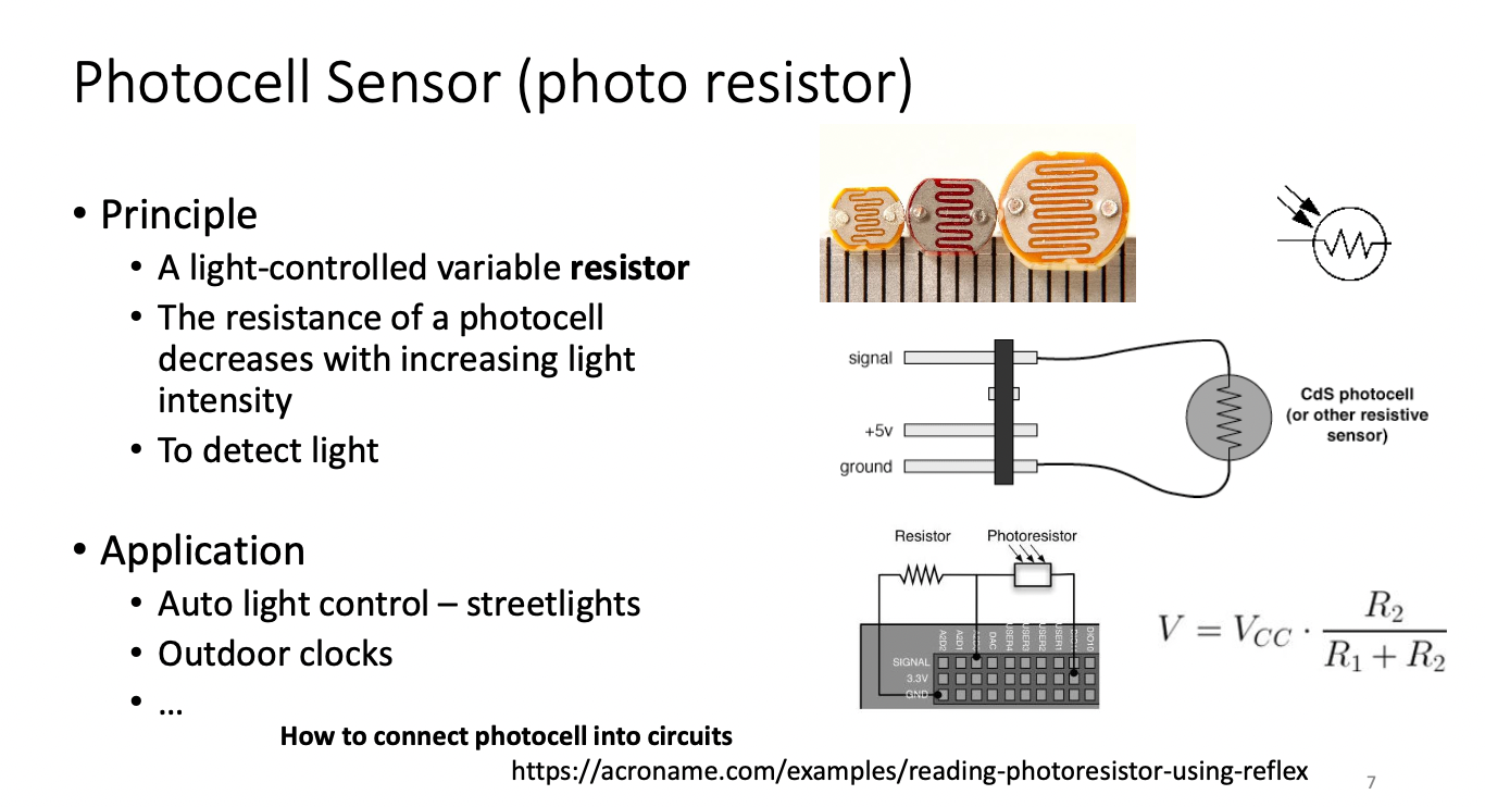
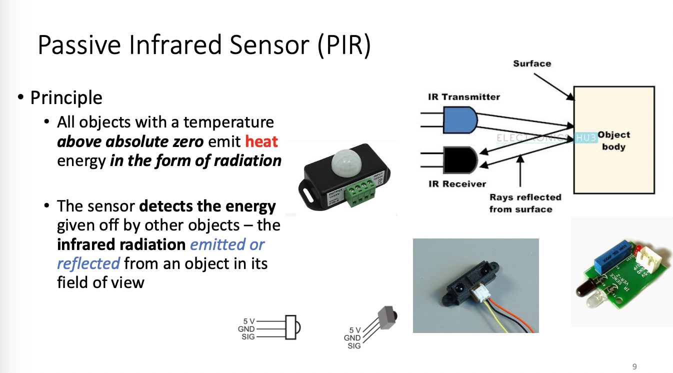
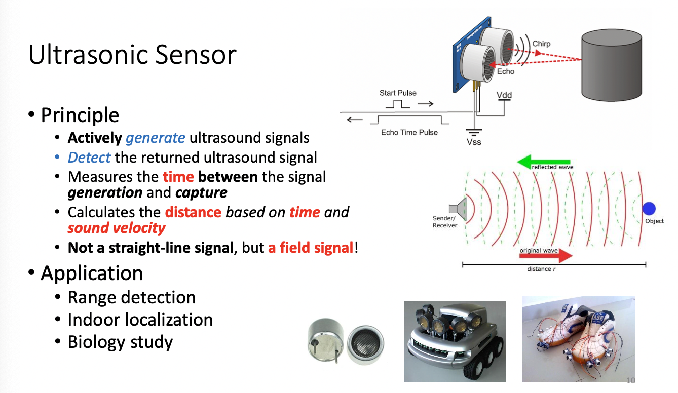
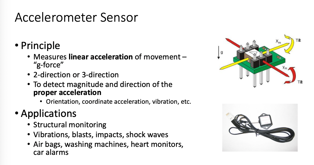
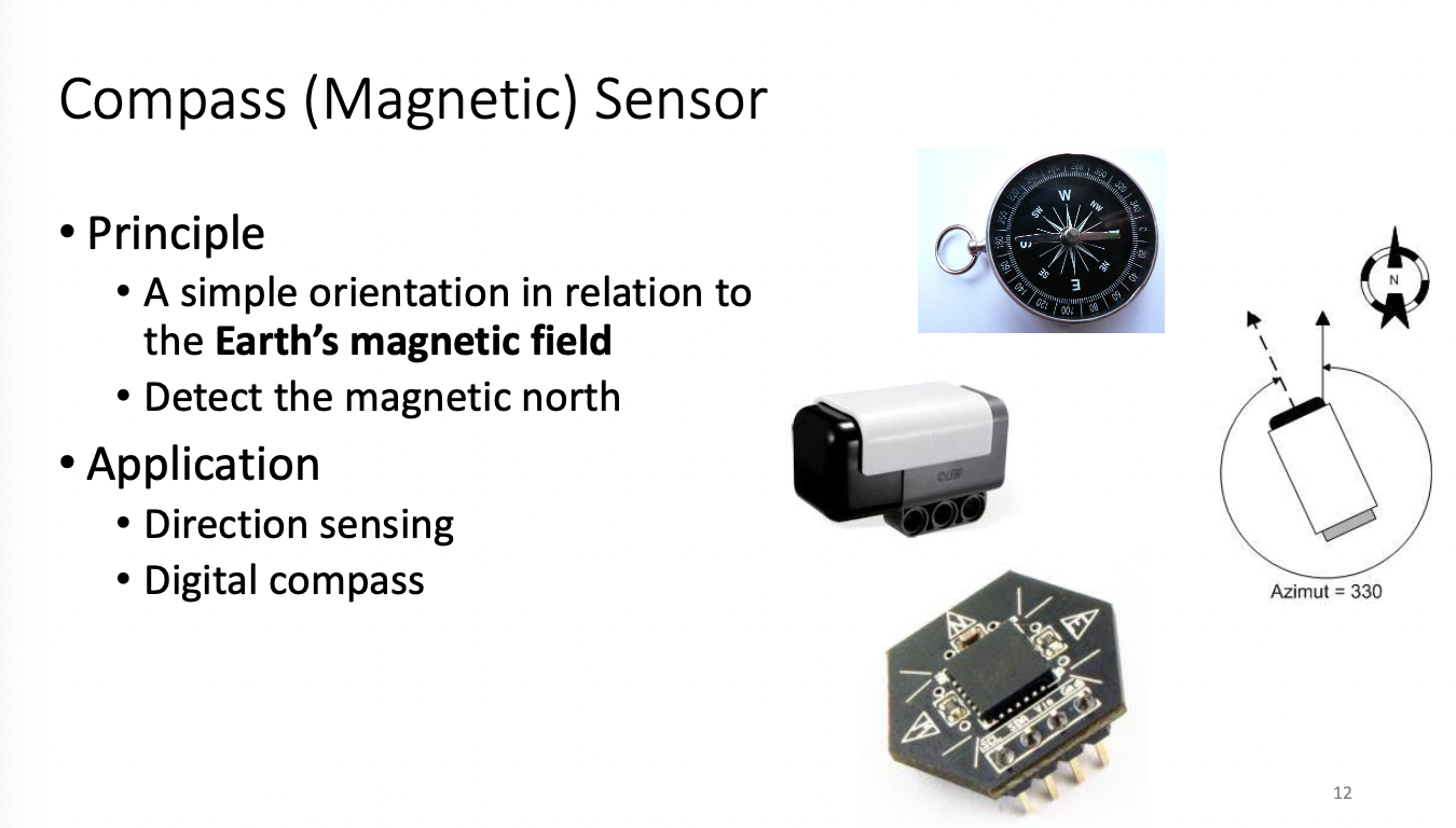
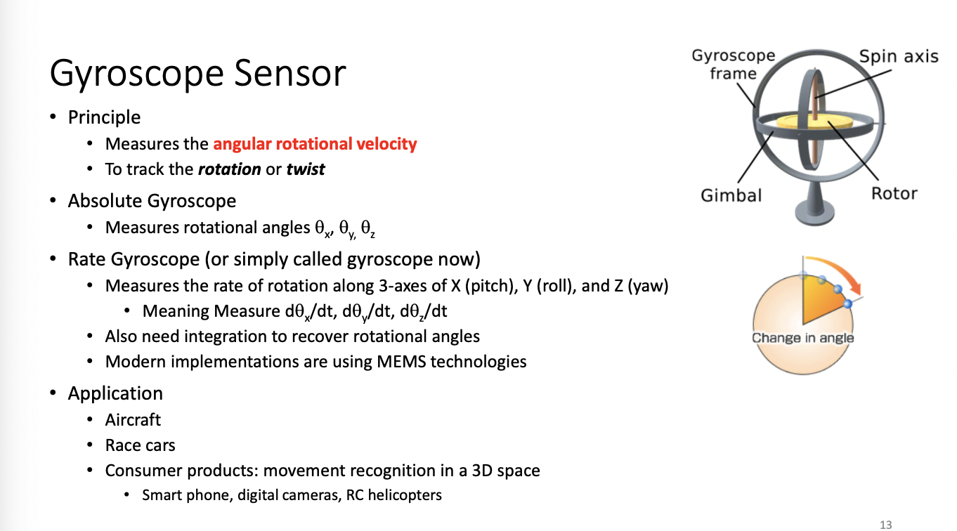
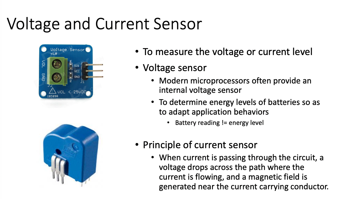
How to read sensor data
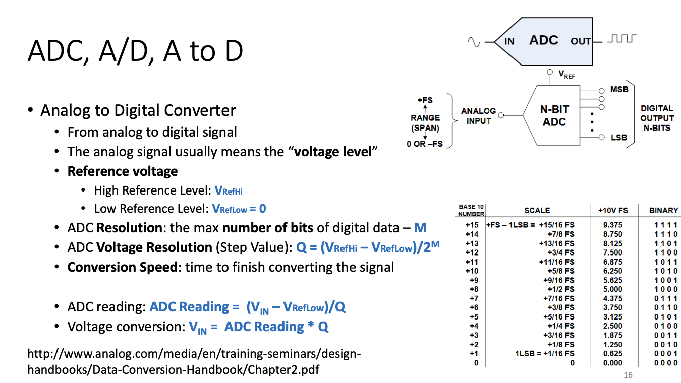
Analog usually means "Voltage Level"
Reference voltage
- High Reference Level: VRefHi
- Low Reference Level: VRefLow = 0
ADC Resolution: The max number of bits of digital data - M
ADC Voltage Resolution (Step Value):
Conversion Speed: Time to finish converting the signal
ADC reading: ADC Reading =
Voltage Conversion:
Binary Number(code) -> Voltage (Output from Sensor) -> Physical
ADC Is usually a look up table that compares measured voltage to a value that's stored into ADC data register which your code reads through the bus
ADC Reading would then also =
and Vin =
Max number for ADC =
Analog Reference Voltage changes the high reference
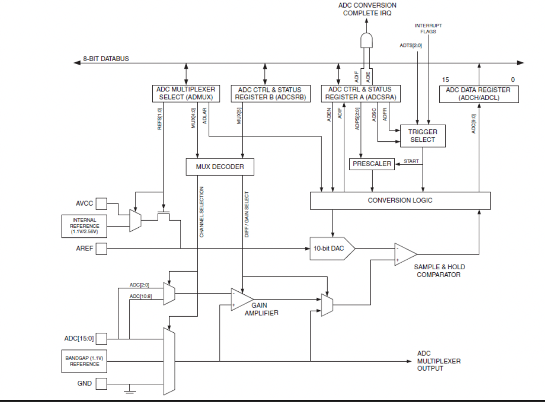
This conversion takes several clock cycles
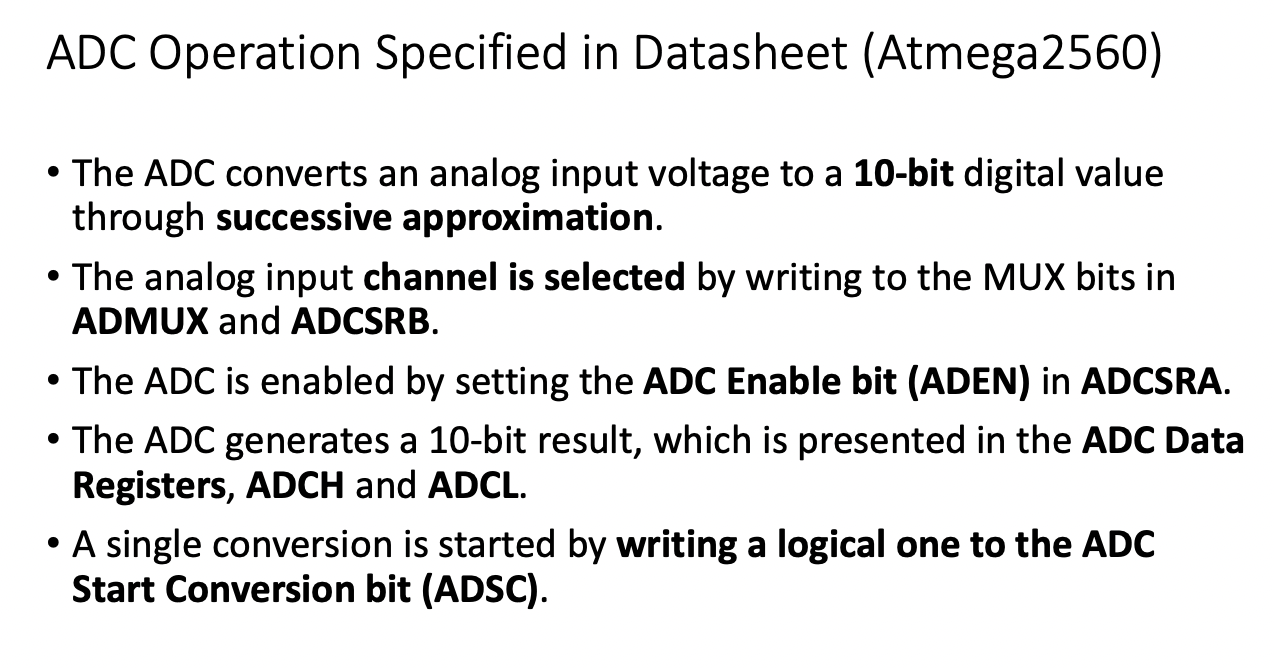
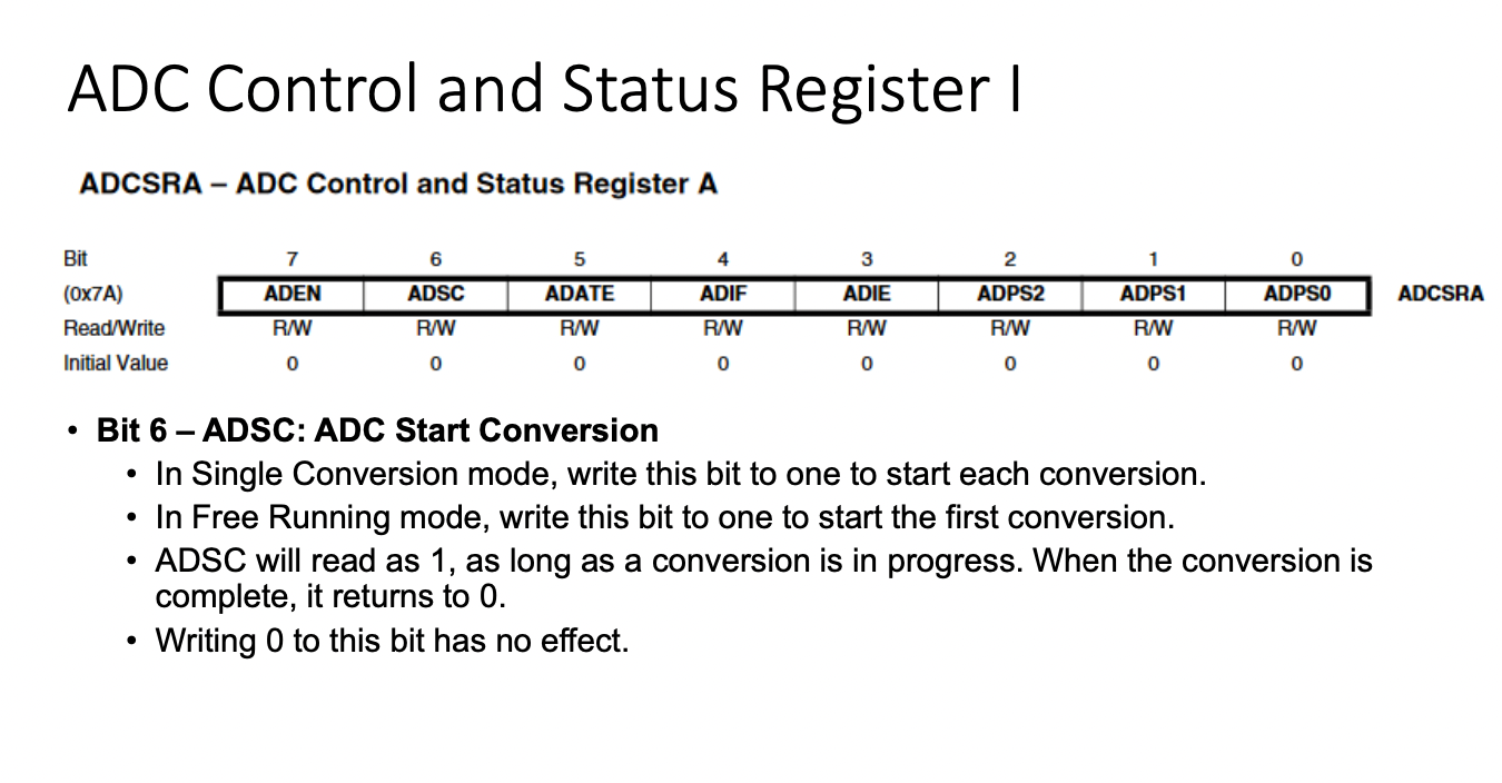
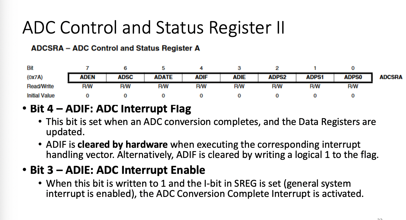
Pay attention to ADIF is cleared by hardware when executing the corresponding interrupt. Some systems will not clear this automatically.
ADCSRA AD Converter Status Register Address
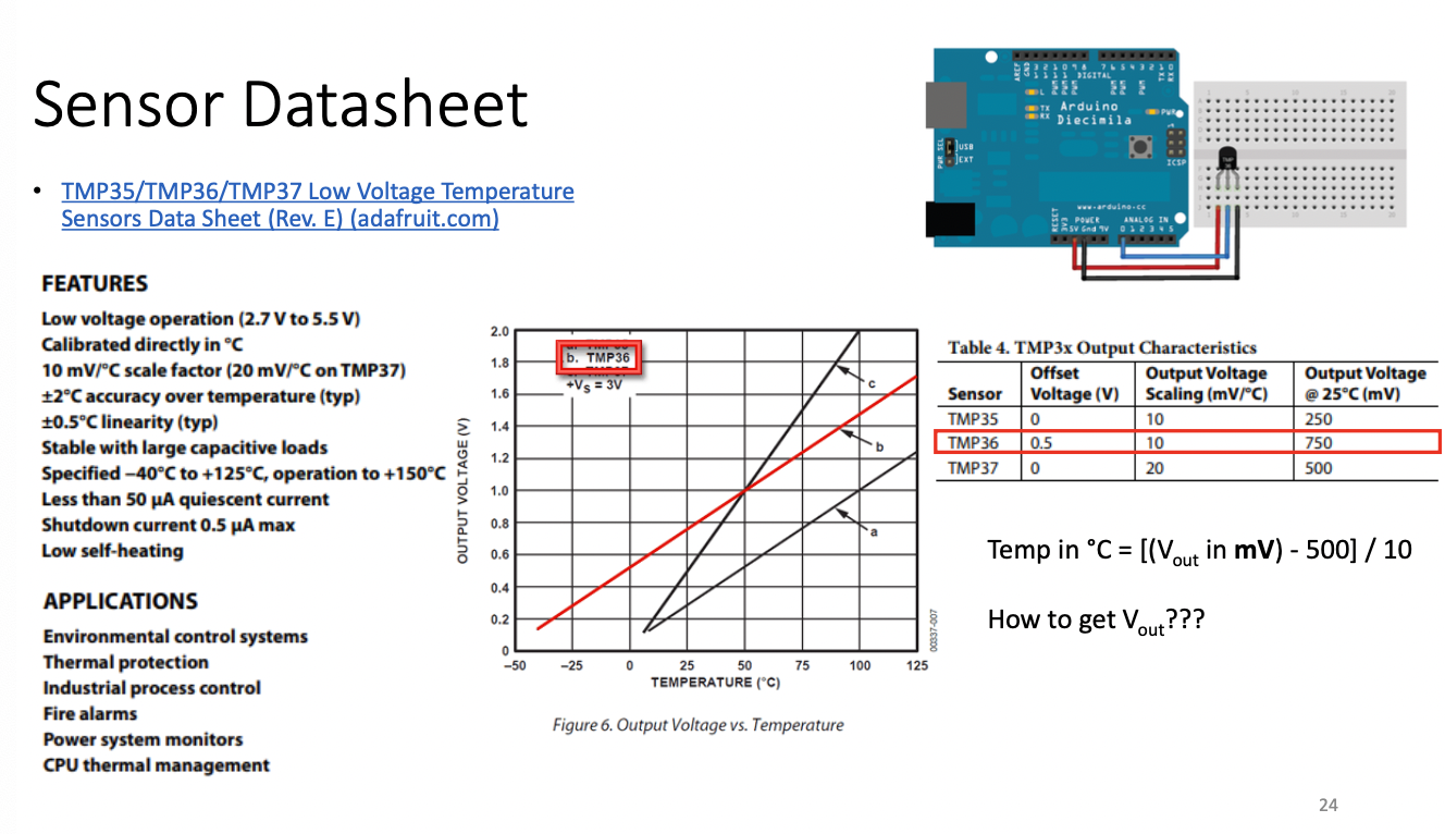
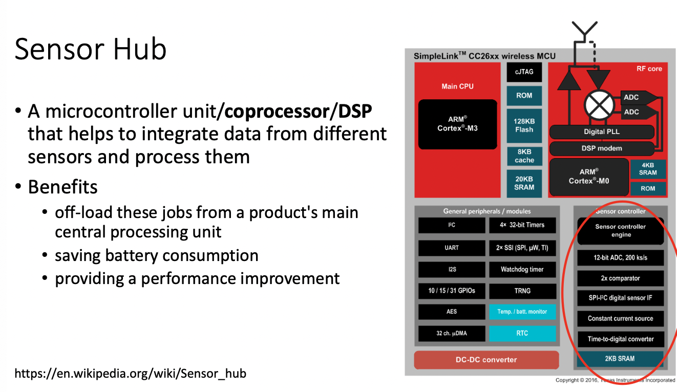
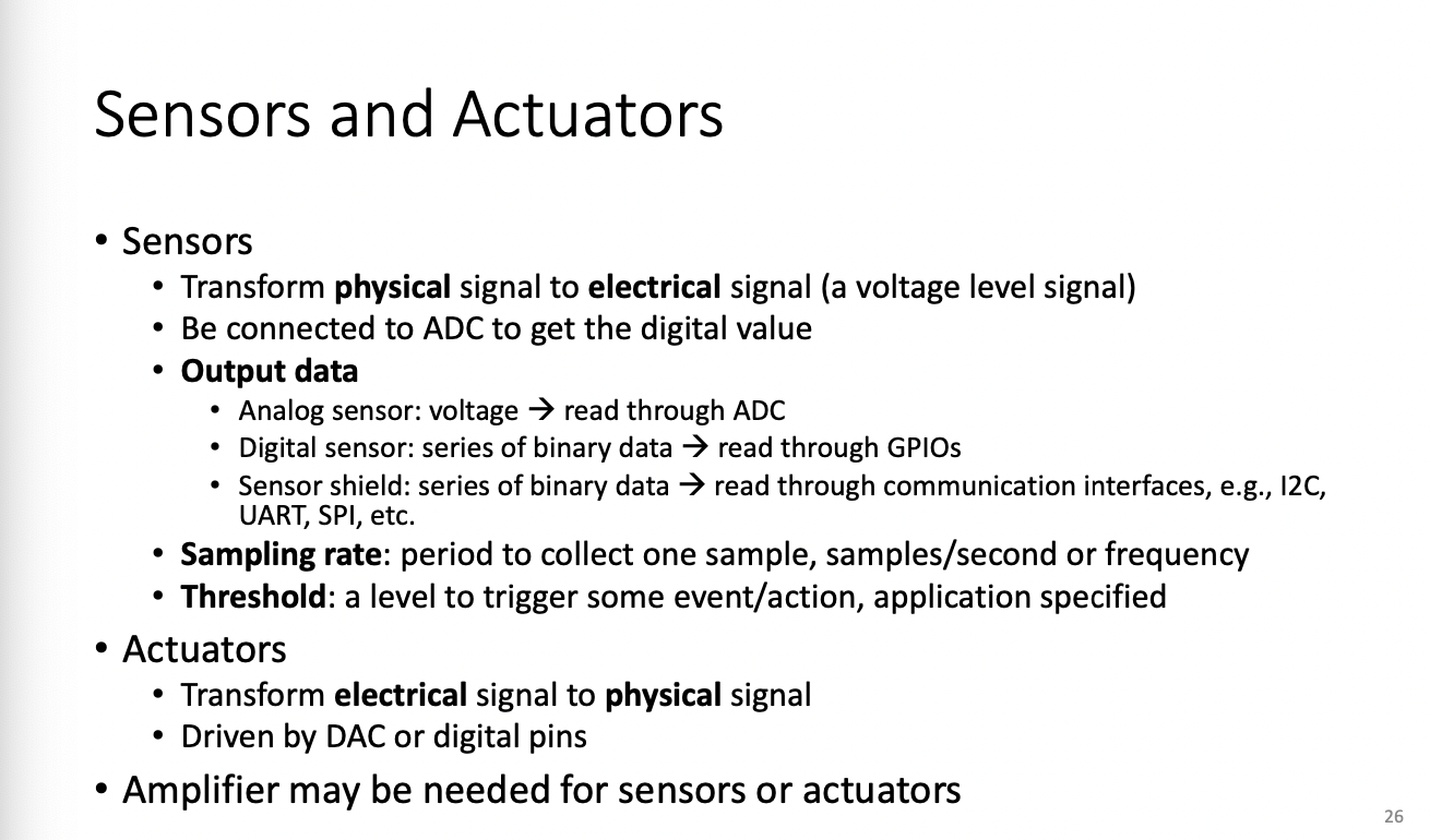
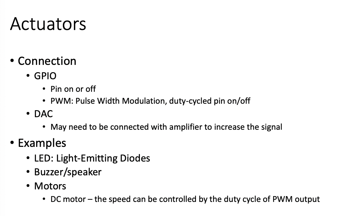
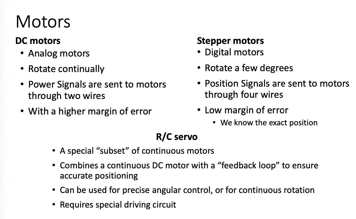
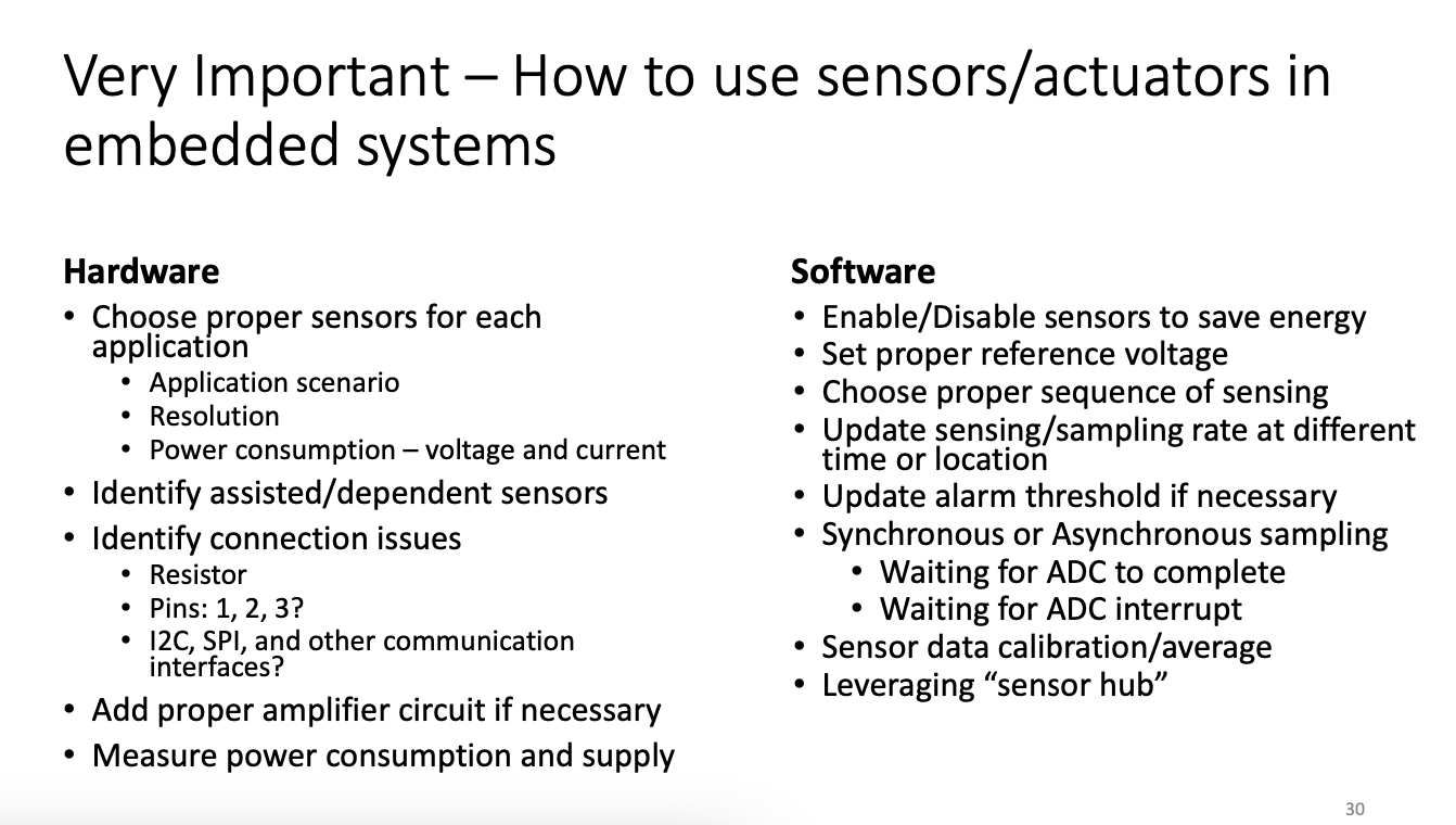
VERY IMPORTANT ^^^
Lecture Day 5
Interrupts
(Simon - Chapter 4) MOST IMPORTANT TOPIC
- Interrupt: a signal to the processor emitted by hardware OR software indicating an event that needs immediate attention
The signal is called Interrupt Request or IRQ
Whenever and interrupt occurs, the controller completes(aborts) the execution of the current instruction and starts "processing" the interrupt request
The execution of the current instruction is not aborted, but the current code logic may be broken!
RESET ALWAYS HAS HIGHEST PRIORITY
Why Do We Need Interrupts?
Handshaking - Asynchronized events, but synchronized behavior
Quick Response
- You can't keep waiting or predict the next event accurately
Interrupt(shopkeeper) vs. Polling(salesperson)
- Polling may be slow in response, depending on polling interval
- Polling may consume more resources: energy, CPU time, etc
- Polling may need more software support: bug
When to use interrupts?
- To detect events
- to wake up the processor
- Examples
- Watchdog
- timer
- ADC conversions
- Data transfer completion
- SPI, i2c, UART
- External device readiness
- EEPROM and Flash memory read and write completion
Interrupt Categories
- Software Interrupt
- a signal caused either by an exceptional condition or a special instruction in the instruction set
- A signal triggered when a software program is executed by the processor
Hardware Interrupt
- an electronic alerting signal sent to the processor from a hardware device
- the device can either be within or outside of a microprocessor
- the CPU does not know when this would happen
Software Interrupt
- An exceptional condition in the processor itself
- also known as a Trap or Exception
- Example, Divide by zero exception thrown by ALU
- OS will catch exception (current execution logic is preserved)
- then either abort execution
- or ignore exception
- A special instruction in the instruction set(within the CPU)
- Subroutine Calls
- Data read or write requests from a disk controller
- There can be hundreds of Software interrupts
- Processor does not need to abort its execution immediately
- code logic may be protected
Hardware Interrupt
- Hardware interrupts are asynchronous and can occur in the middle of code execution
- Components
- External
- Peripheral Devices
- Interrupt Pins
- Internal
- Internal Peripherals - There are limited number of hardware interrupts
- How do we address this?
- Processors typically have an internal interrupt mask which allows software to ignore all or specific hardware interrupts
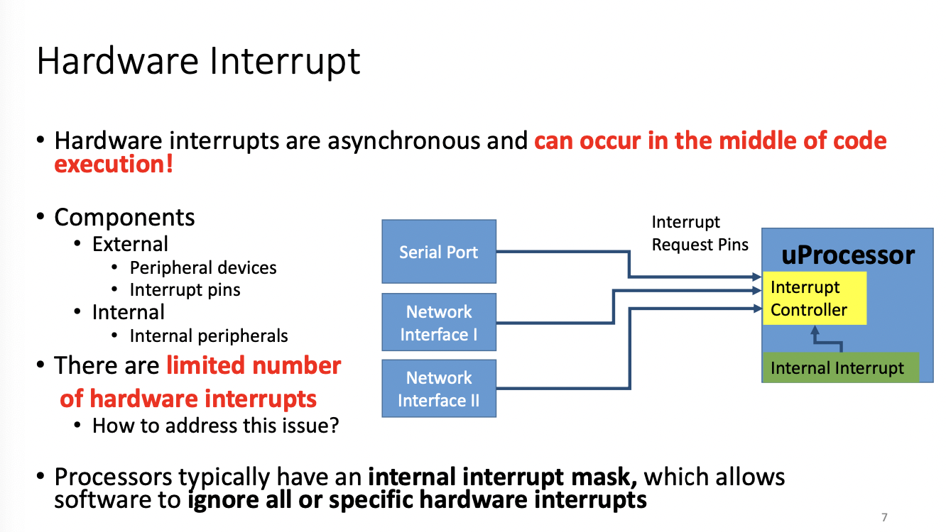
In most cases you need to save the status registers/store data from the register
Look for "interrupt enable" if you're trying to find out what the interrupt is
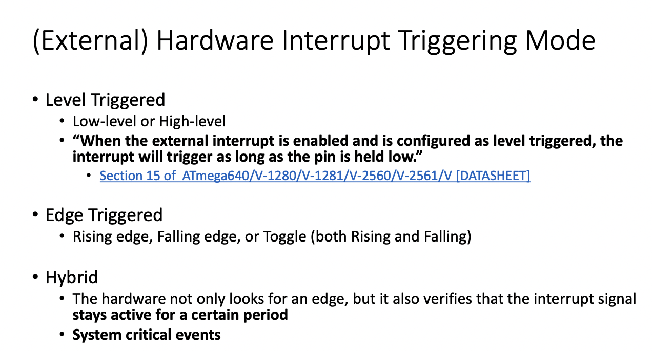
Level Trigger mode is not typically used
We prefer edge triggered
Hybrid -
- Hardware not only looks for an edge, but also verifies that the signal stays active for a certain period
- system critical events
(think nuclear launch...you detect a launch, but you want to make sure that you're actually under attack)
PIC: Programmable Interrupt Controller
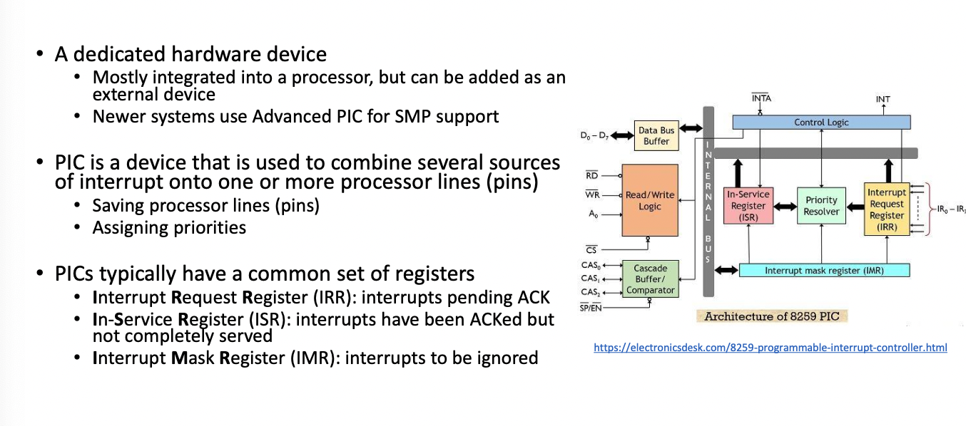
If processor is ready, it changes read enable
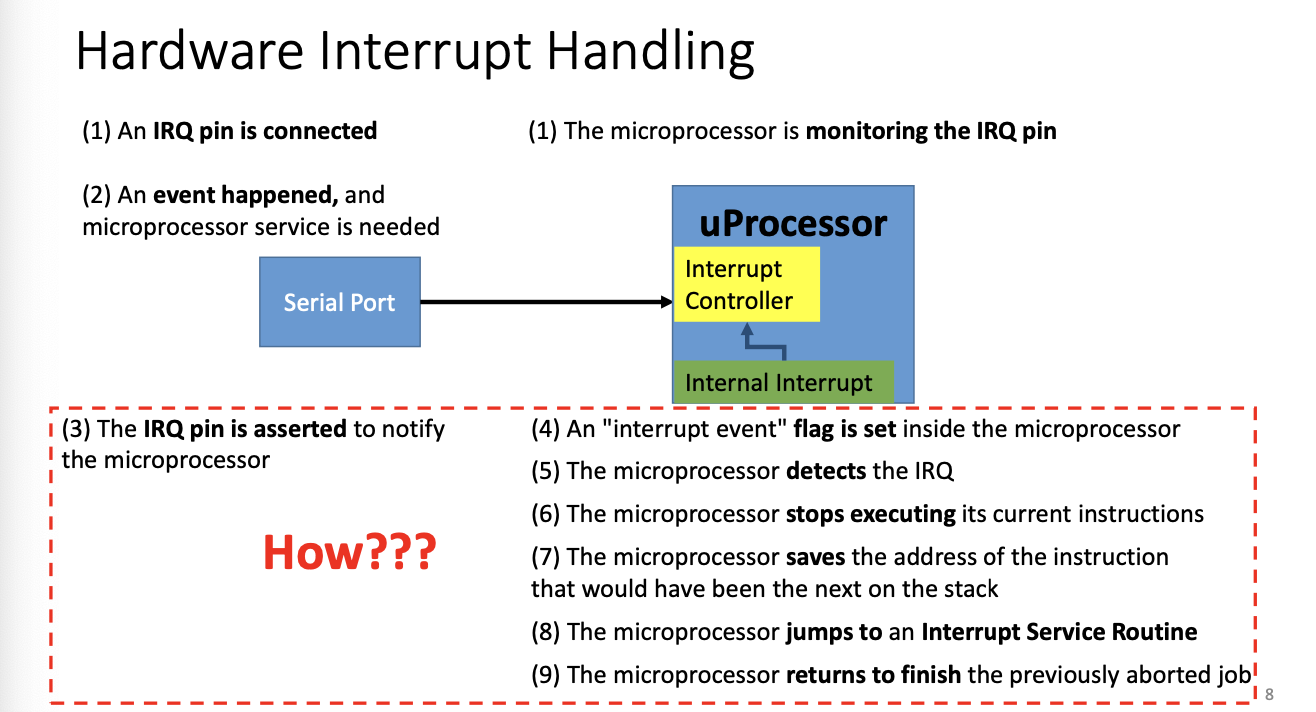
Hardware Interrupt Handling
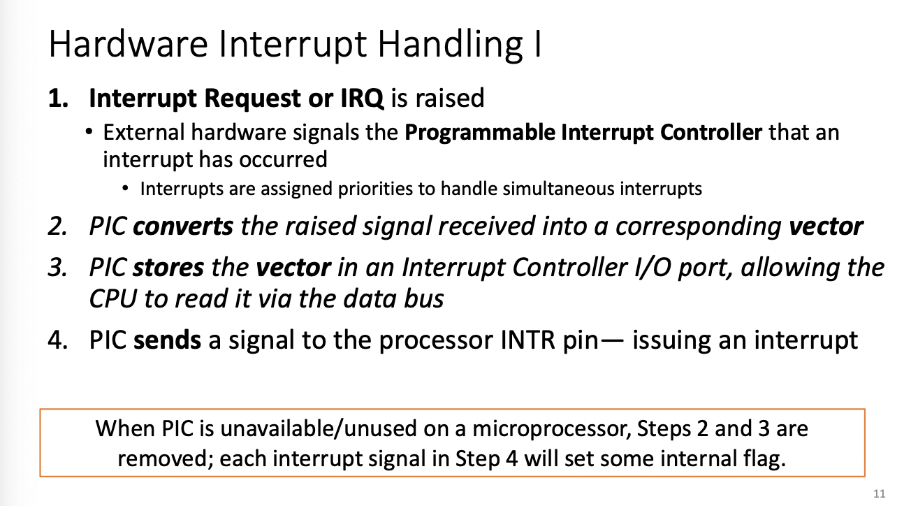
- Interrupt request (or IRQ) is raised
- External hardware signals the PIC that an interrupt has occured
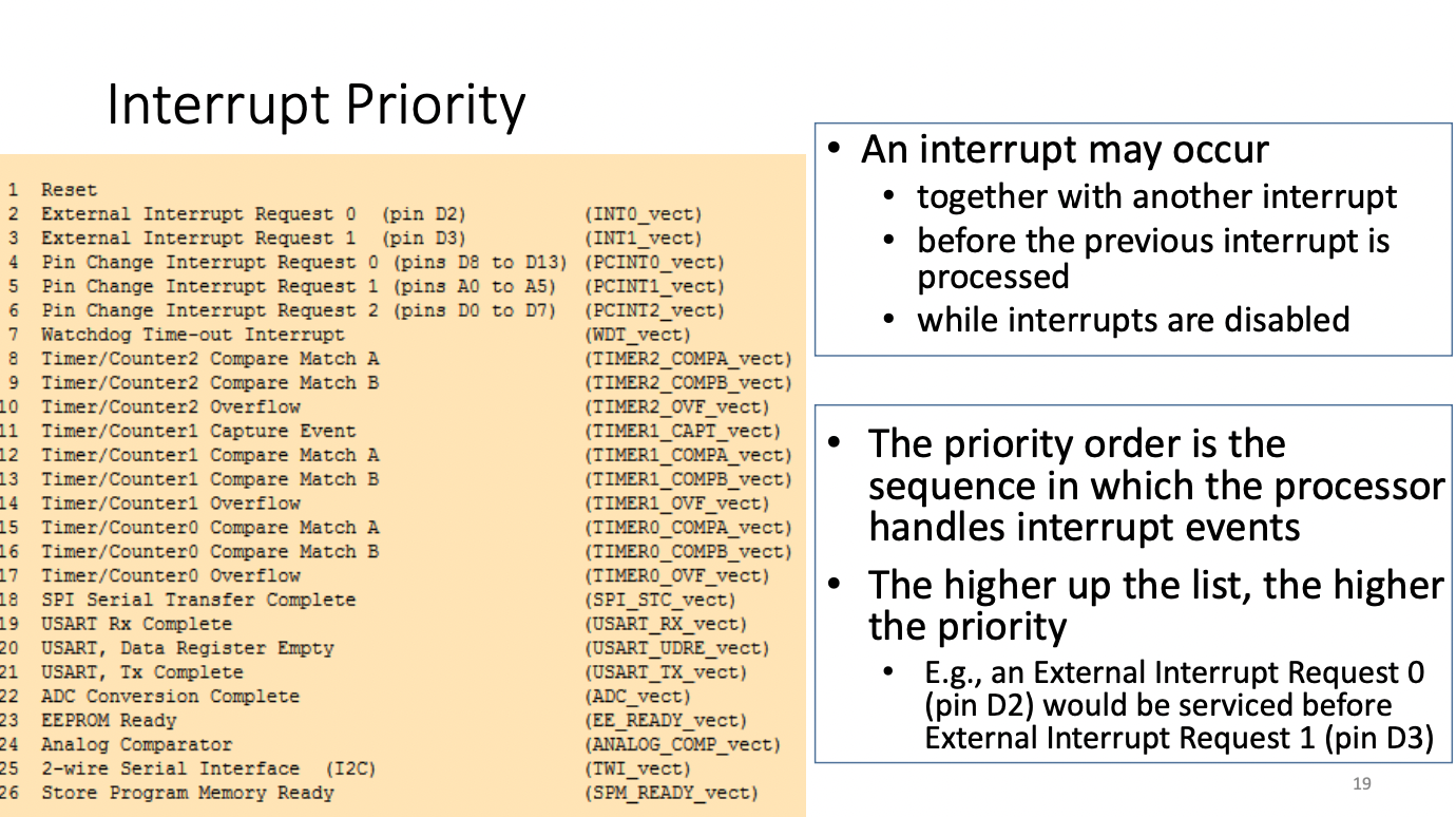
- Interrupts are assigned priorities to handle simultaneous interrupts
- External hardware signals the PIC that an interrupt has occured
- PIC converts the raised signal received into a corresponding vector
- PIC stores the vector in an interrupt controller I/O port, allowing the CPU to read via data bus
- PIC sends a signal to the processor INTR pin - issuing the interrupt
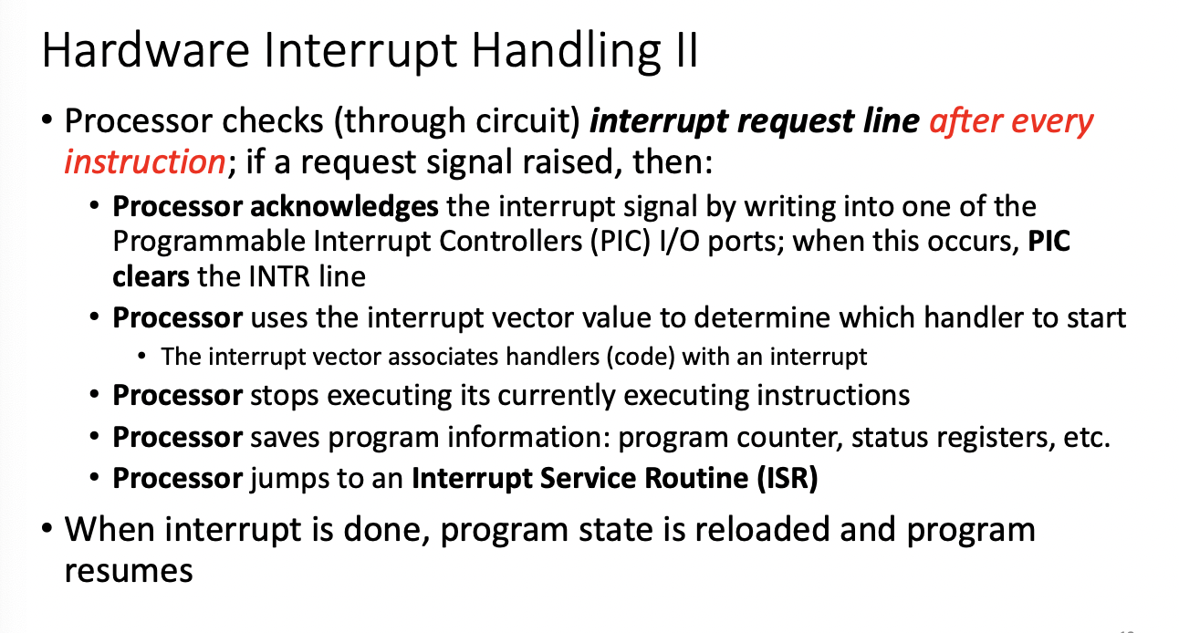
- Processor checks (through circuit) interrupt request line after EVERY instruction, if a signal is raised
- processor acknowledges, PIC clears intr line
(if not PIC, it's already defined) - Processor uses the vector to determine which handler to start
- int vector associates handlers (code) with interrupt
- Processor stops executing it's currently executing instructions
- Processor saves the program info: counter, status registers etc
- Processor jumps to Interrupt Service Routine (ISR)
- processor acknowledges, PIC clears intr line
- When interrupt is done, program state is reloaded and program resumes
Interrupt Service Routine
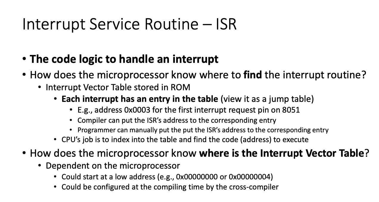
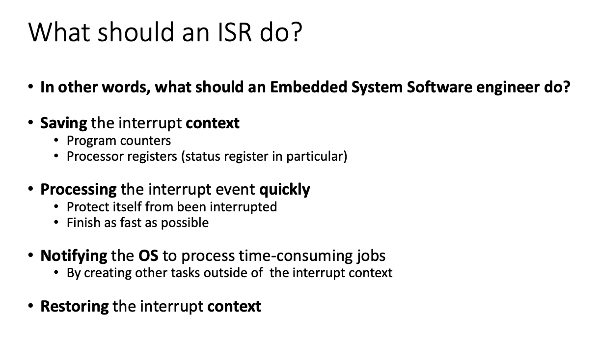
Main job is processing the interrupt even quickly
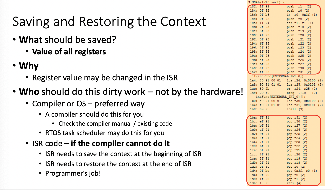
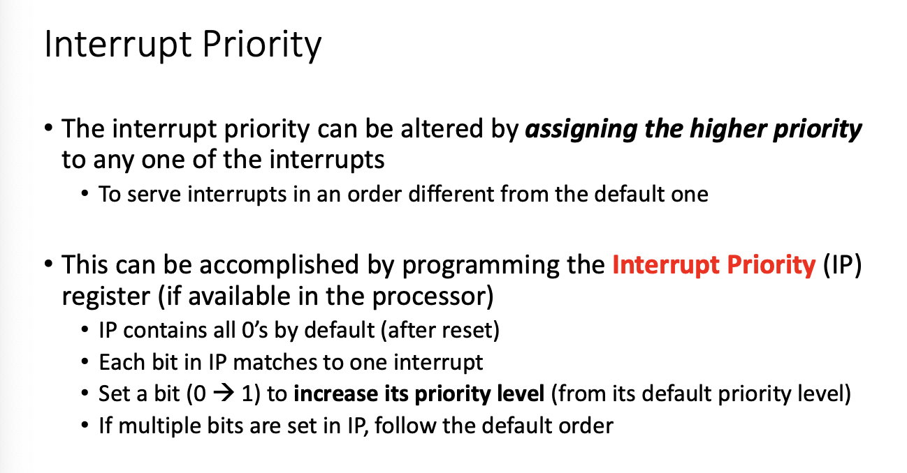
cli() clear interrupt flag
lab3 -noInterrupts();
sleep_disable();
wdt_disable() - watchdog disable
The Problem with Interrupts
ISR, no passing parameter, no return value
Look out for global variables
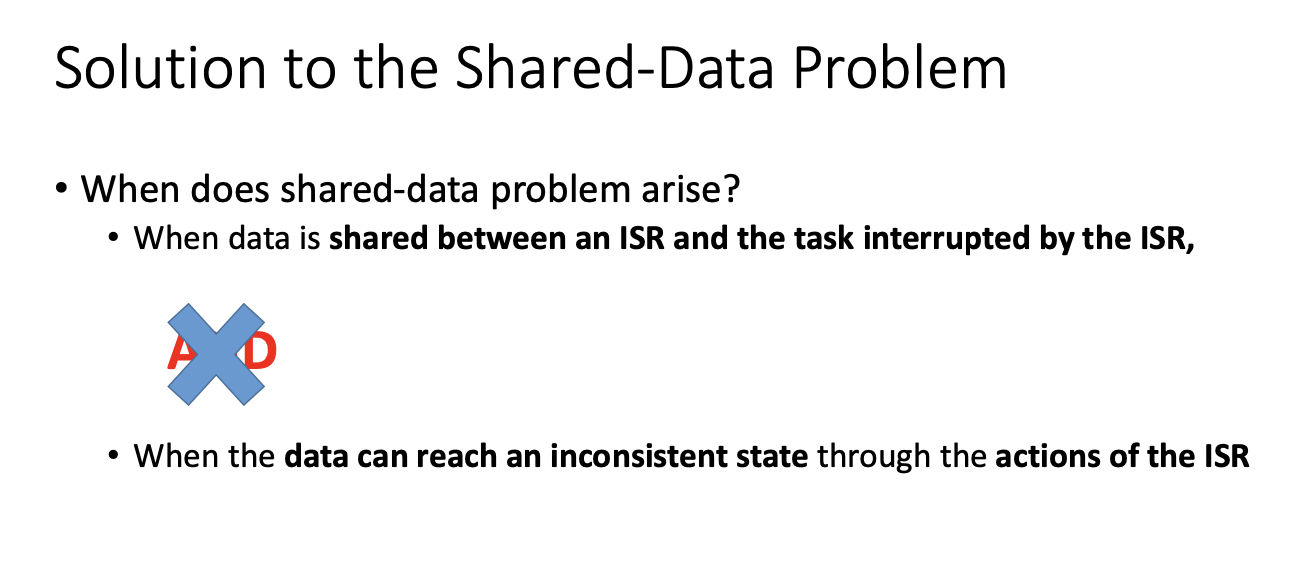
When does shared data problem arise?
- When data is shared between an ISR and the task interrupted by the ISR AND When the data can reach an inconsistent state through the actions of the ISR
The difficult part? does the bug appear consistently? - different platforms
Will it show up during testing? timing issues
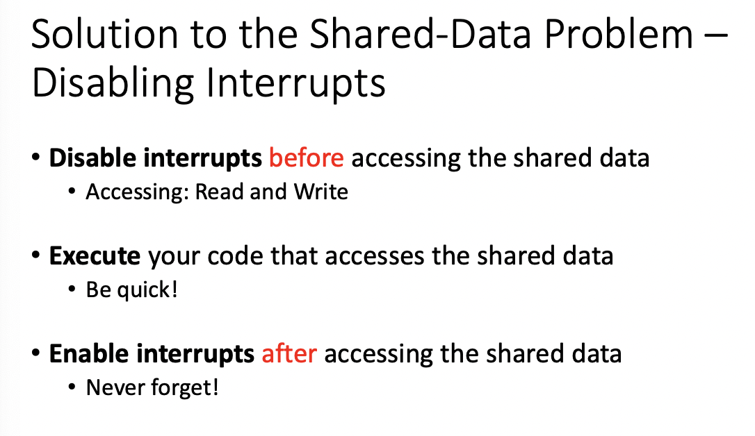
Solution to Shared Data Problems
- Disable interrupts before accessing shared data
- Execute your code that accesses shared data
- Enable interrupts after accessing shared data
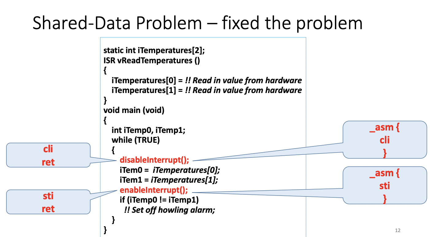
Why disable all interrupts?
Why not just disable the specific ones?
Arguable Reasons
- interrupts are disabled only briefly
- assume your ISR code is not long
- Increasing response time by a few instructions is not a big deal
- the overhead of disabling single intterupt is generally higher
Disabling all interrupts is a simple, one size fit all solution
critical ones cannot be disabled
It's ALL YOUR JOB
the compiler cannot help you - it's not that smart
TOOLS cannot help you, they're not that SMART
- it may help you identify that you are using shared data
- it may post warnings that shared data is not protected
But you are responsible for your code to ensure correctness
ATOMIC OPERATION
Atomic: a part of program is atomic if it cannot be interrupted
- MOST machine code instructions are atomic
- a single line of c code is rarely just one instruction
Critical Section: a set of instructions that must be atomic for correct operation
shared data problem arises when task code accesses shared data non-atomically
atomic is recognized keyword
VOLATILE KEYWORD
Static VOLATILE will force the value to be read every time it is referenced - ALWAYS ACCESS FROM MEMORY
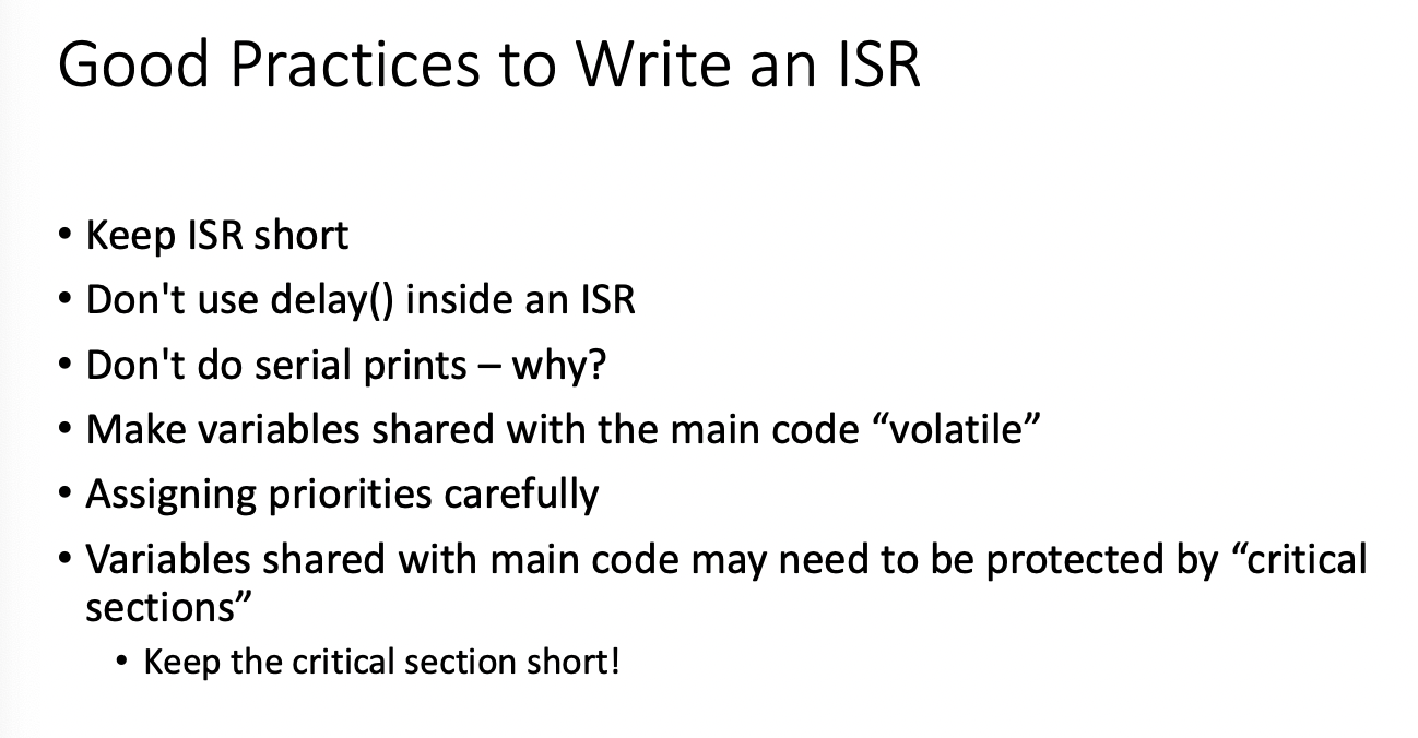
- Good Practice: Variables shared between ISR and NORMAL FUNCTIONS should be declared volatile
This tells the compiler that such variables might change at any time and thus the compiler must reload the variable from memory whenever you reference it rather than relying on its copy in a register
it warns the compiler that certain variables may change because of interrupt routines or other things the compiler doesn't know about.
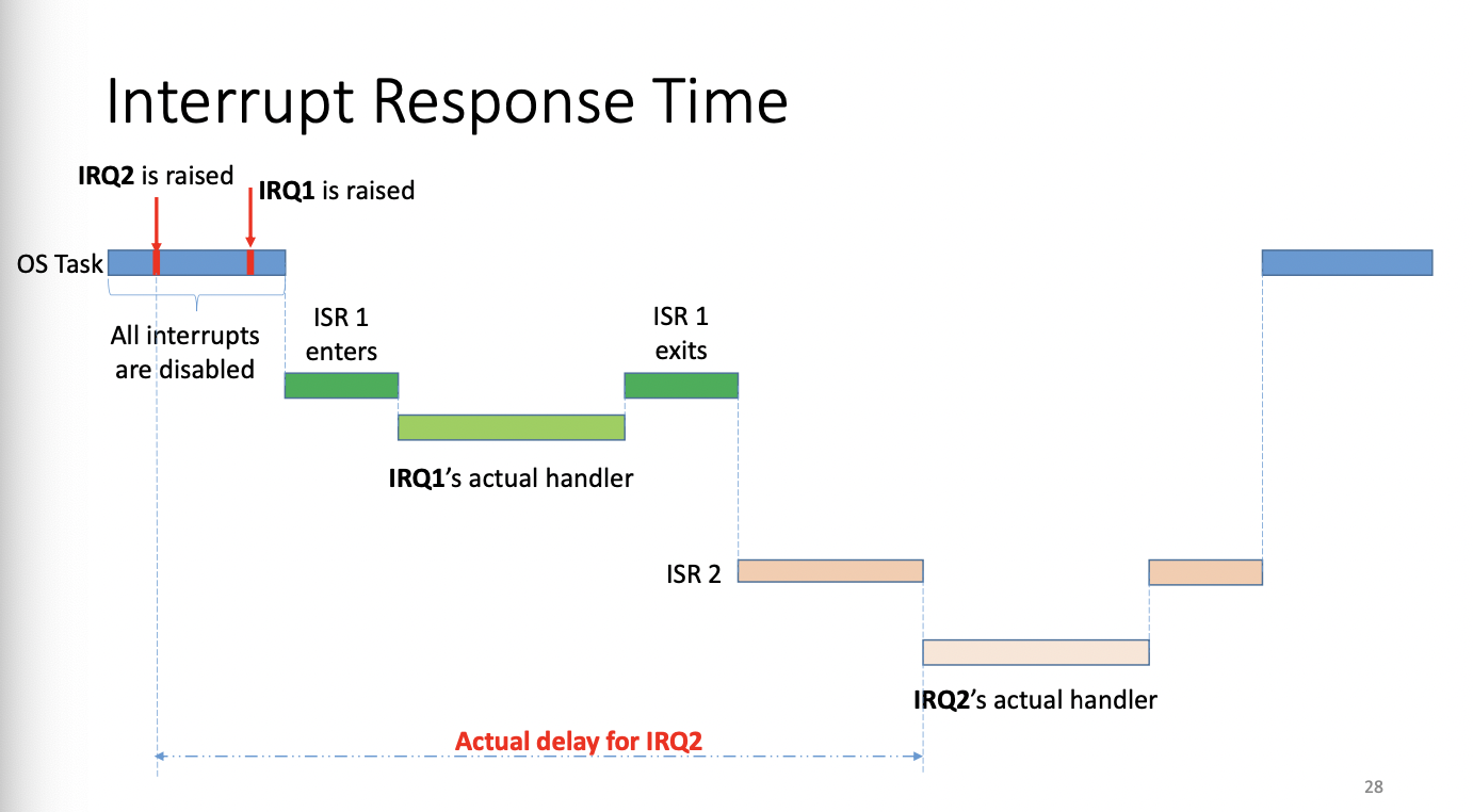
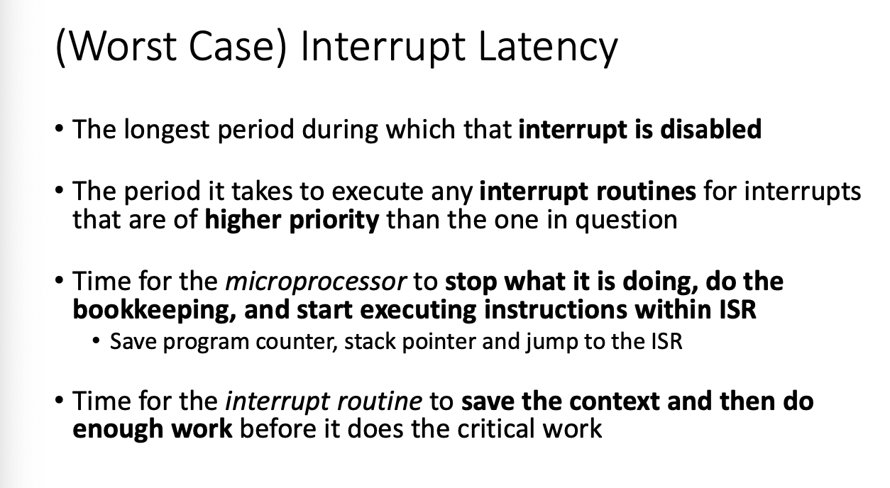
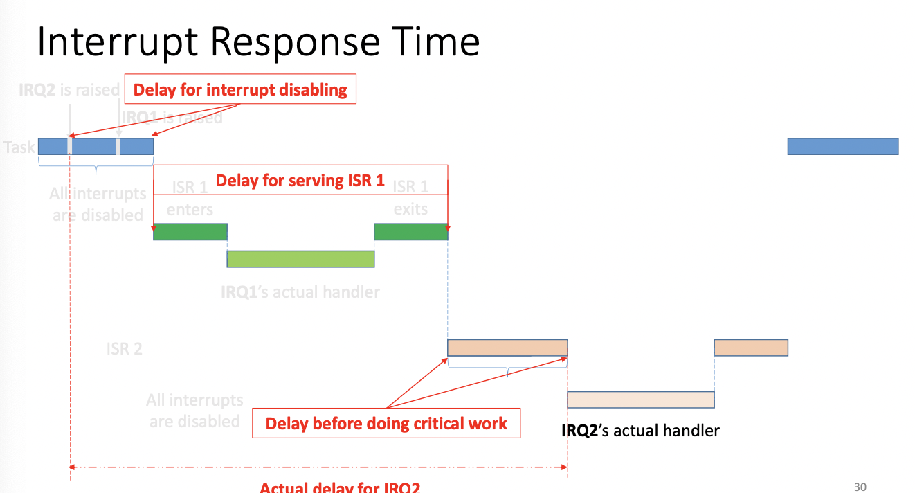
Interrupt Response Time
Data Communication Interfaces
We need communication to talk with other peripherals, sensors, microcontrollers, etc
Within a system
- wired communication
Between Systems
- wired or wireless
Wired Communications
- UART, SPI, I2C, 1Wire, CAN, I2S, USB, Ethernet, ETC
Wireless
- Wifi, Bluetooth, ZigBee, Lora, NFC/RFID, Sub-1G
Fundamentals
Speed
- Bit/Byte Rates: bits or bytes per second
- Baud Rate, Number of signals per second
- including data and extra signaling bits
Addressing
- including data and extra signaling bits
- Central(Host) vs Peripheral(device)
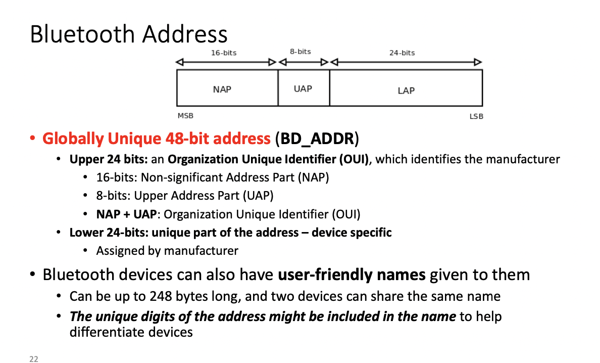
- Globally Unique(mac address) or Locally Unique(device ID)
- Statically allocated vs Dynamically allocated
Required Connections
- GND, VCC, data pins, clock pins
Power Consumption
- critical for wireless communications
Communication modes
- Full Duplex: Both Send and Receive at the same time
- Half Duplex: Devices take turns transmitting and receiving
- Simplex: One direction only with no provision for receiving
Wireless communications typically run in half duplex mode due to collision
- new noise cancelling tech has full duplex wireless communications
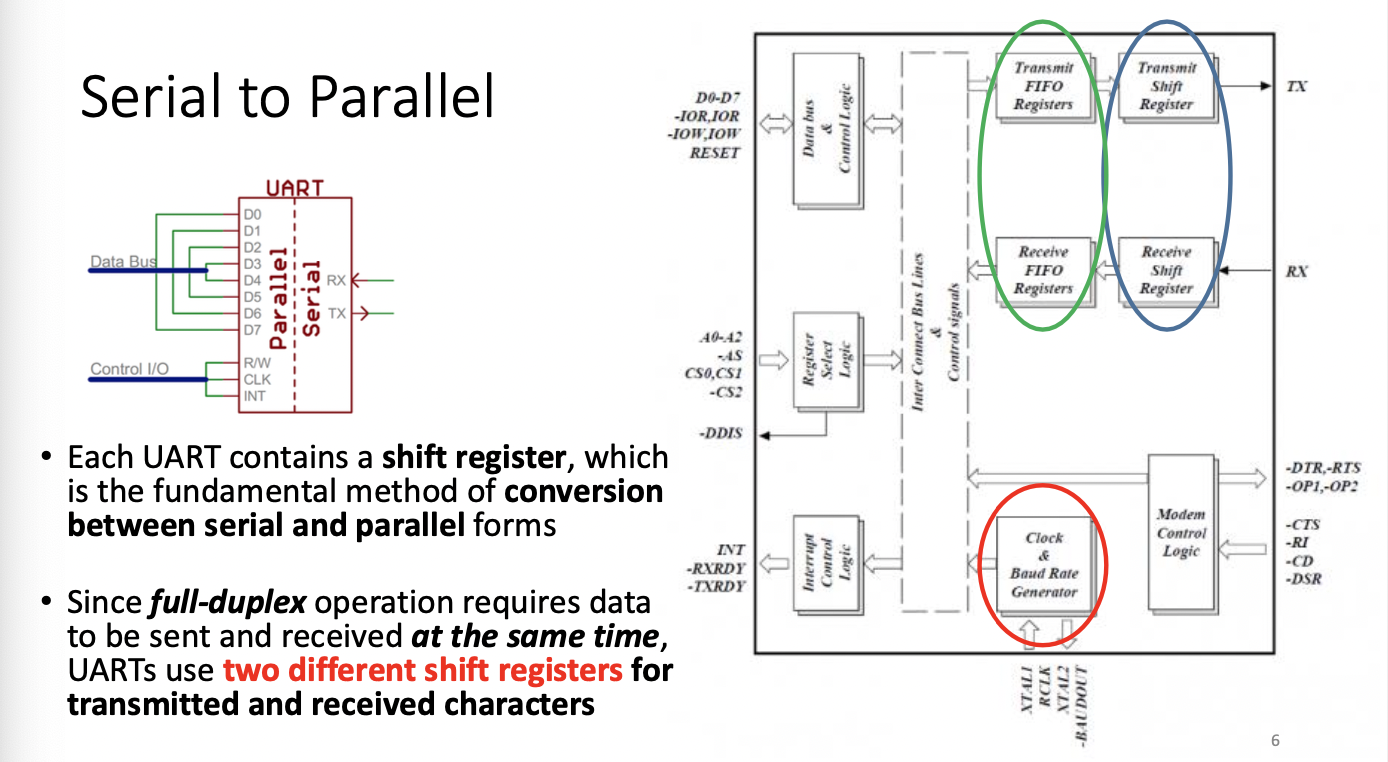
UART - Universal Asynchronous Receiver/Transmitter
USED EVERYWHERE
- Full-Duplex communication
- Data is translated between parallel and serial forms
- Universal: the dat format and transmission speeds are configurable
- only in the relationship of sender and receiver (or peers)
- Sender: takes bytes of data from application and transmit individual bits in a sequential fashion
- receiver take bits of data and reassmbles them into individual bytes
- Serial protocols will often send the least significant bits first (but this is configurable usually)
- UART DOES NOT define electric characteristics, only logic
- the electric signaling levels and methods are handled by an external circuit
- RS-232 is common standard for serial interfaces
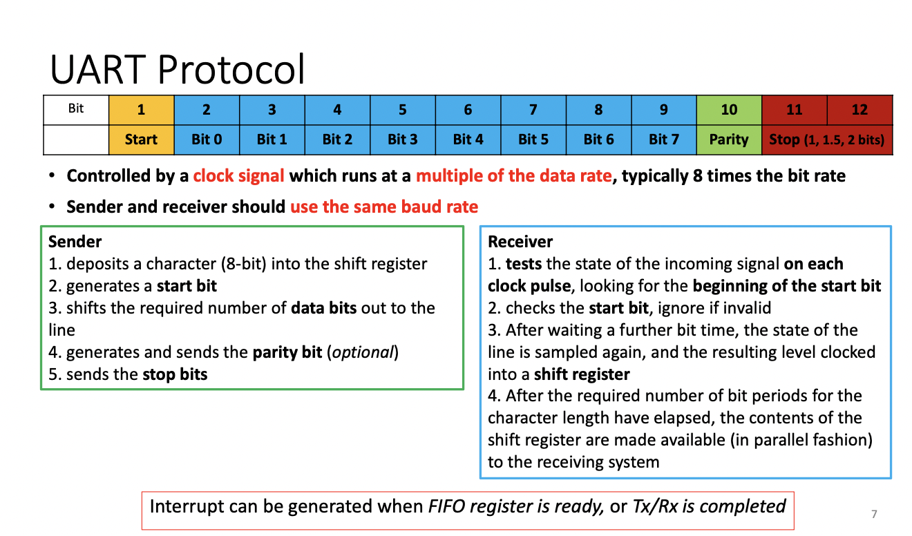
The clock signal tests multiple times for signal
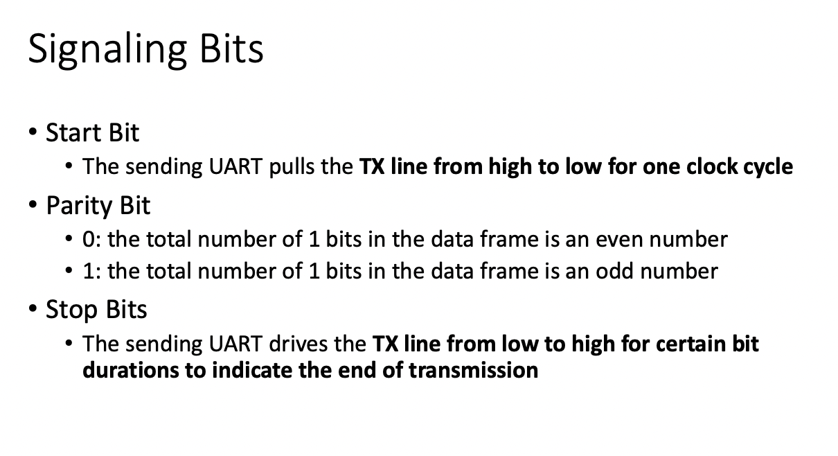
The sender drives the TX line from low to high for a duration to indicate the end of a transmission.
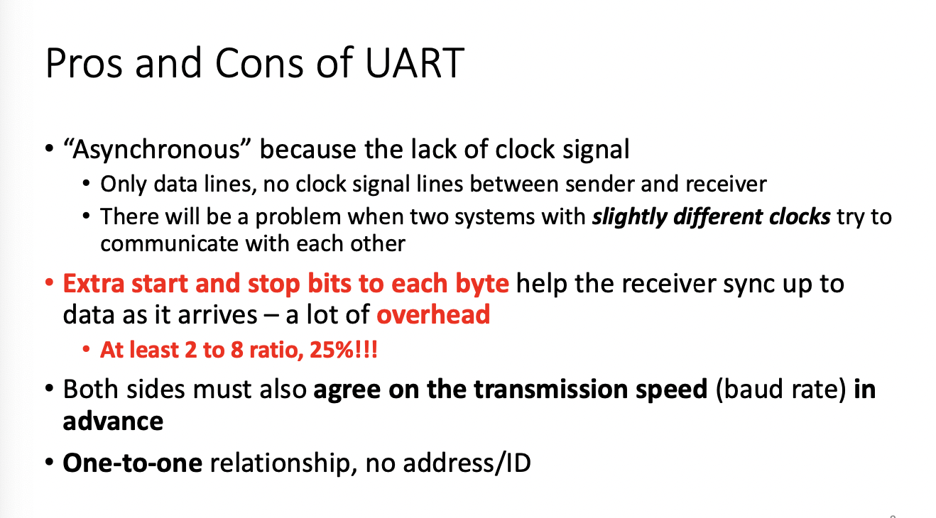
Each device has it's own clock source which may cause issues
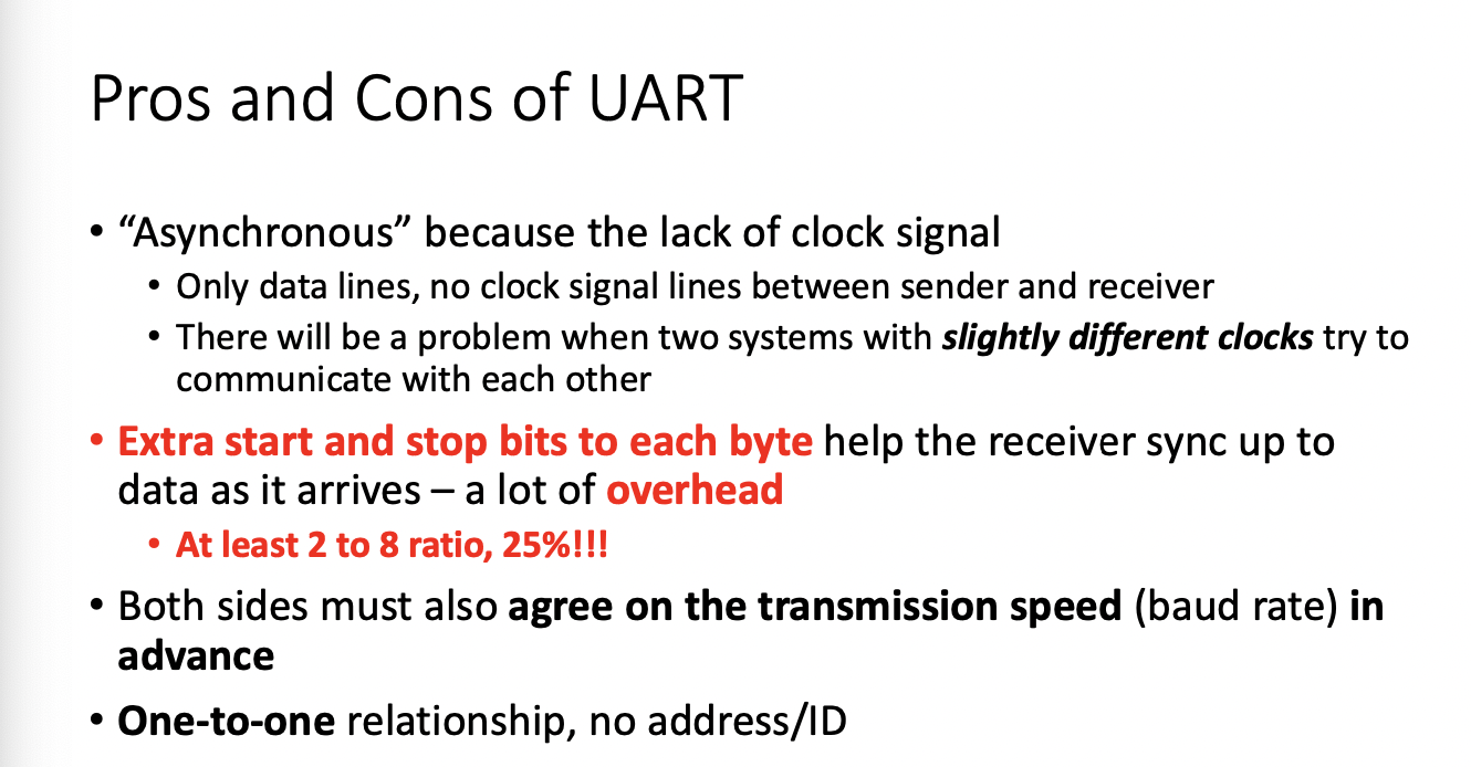
AT LEAST 25% OVERHEAD
Transmission speed(baud rate) must be designated in advanced
One to one relationship - no address
You can use soft serial to implement
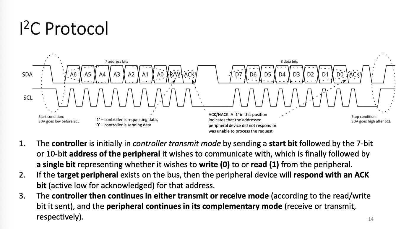
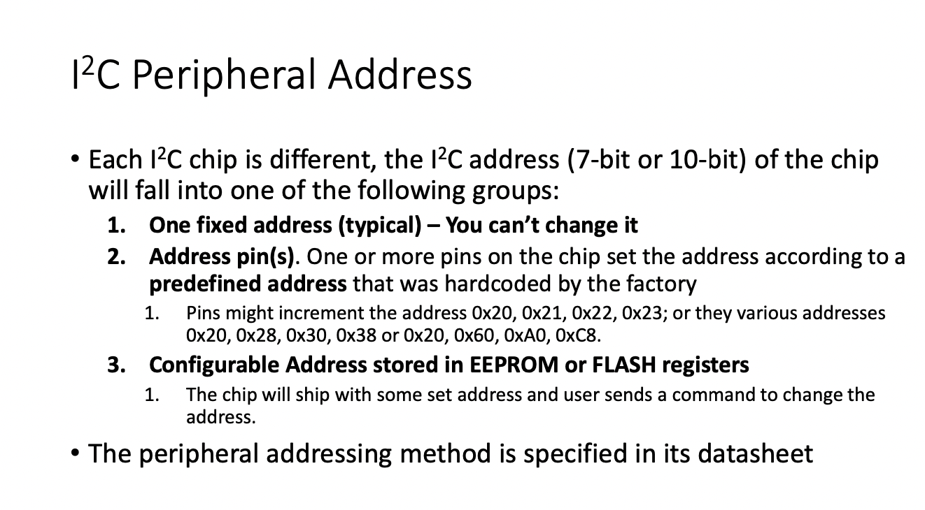
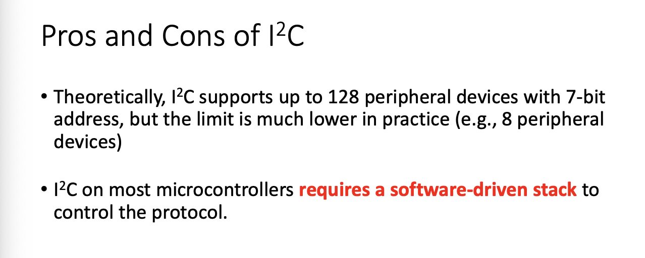
I2C
You can have multiple peripherals and controllers
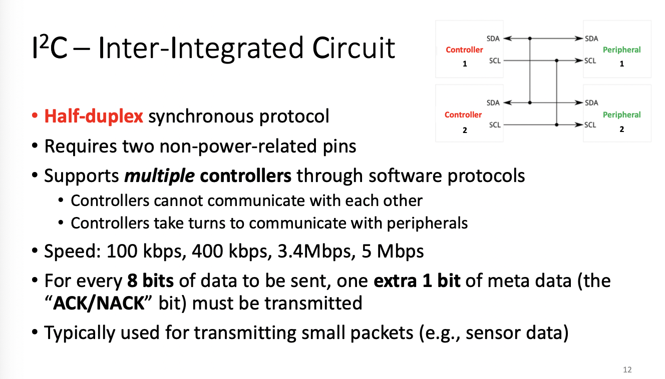
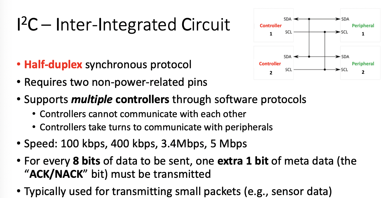
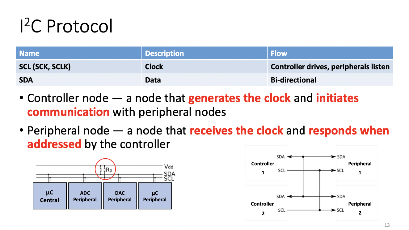
Rp is pull up resistor
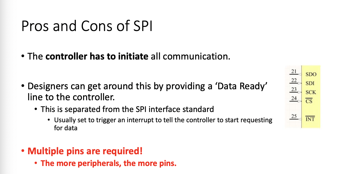
SPI
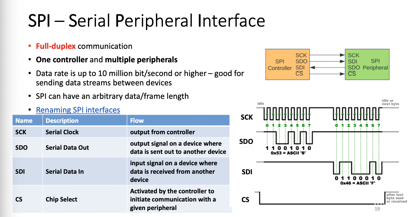
You must use chip select pin to select peripheral (drive signal LOW)
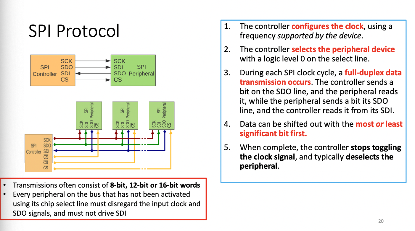
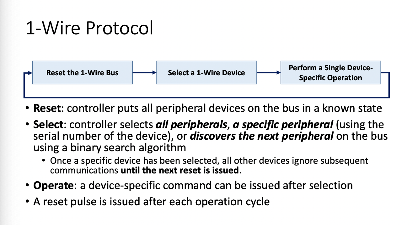
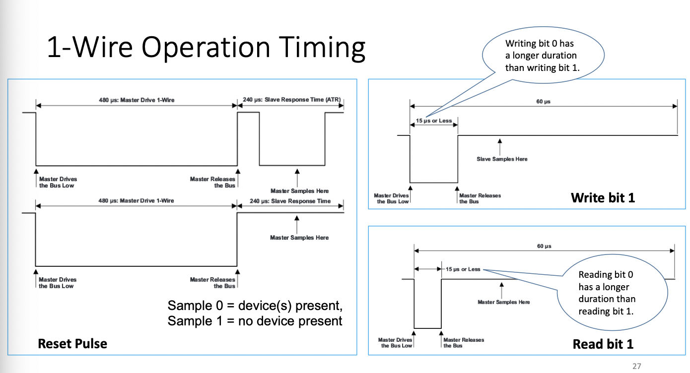
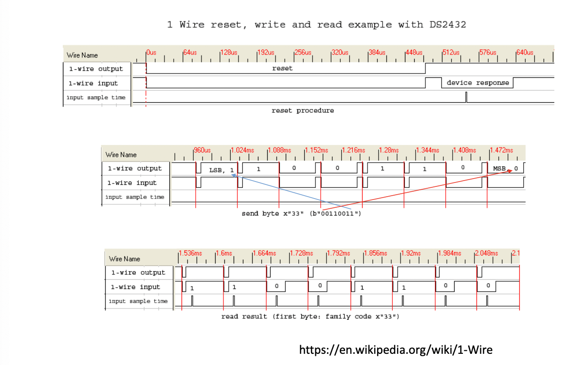
1-Wire
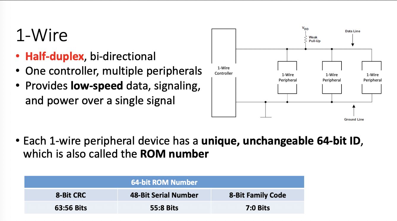
Half-Duplex bi-directional
One controller, multiple peripherals
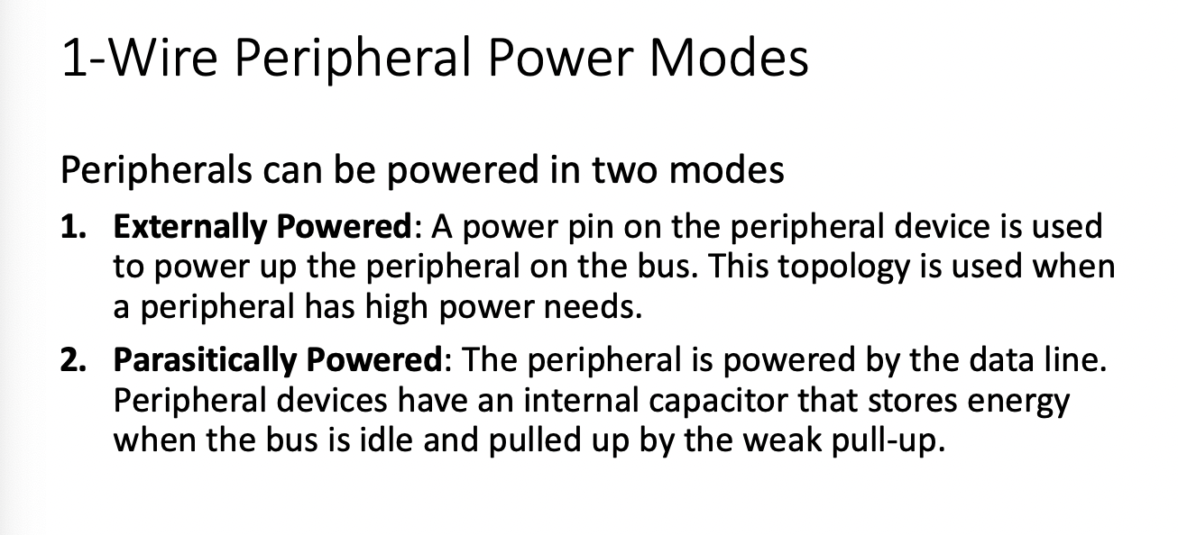
provides low-speed data, signaling, and power
- Each 1-wire peripheral has a unique unchangeable 64bit ID also called the ROM number...many use a capacitor to manage power
Lecture 8 Wireless communications
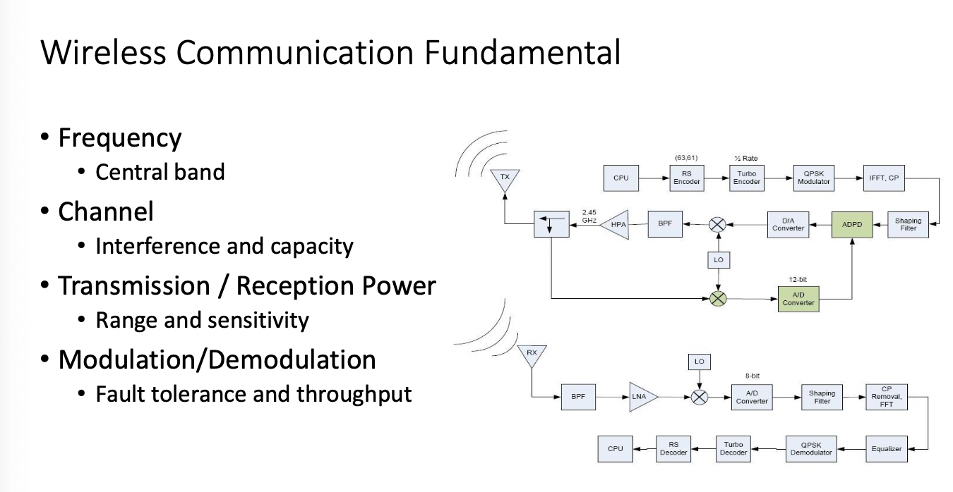
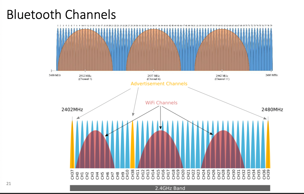
- Frequency
- Central Band 2.4GHZ
- Channel
- Interference and capacity
- Transmission / Reception Power
- range and sensitivity
- Modulation/ Demodulation
- Fault Tolerance and Throughput
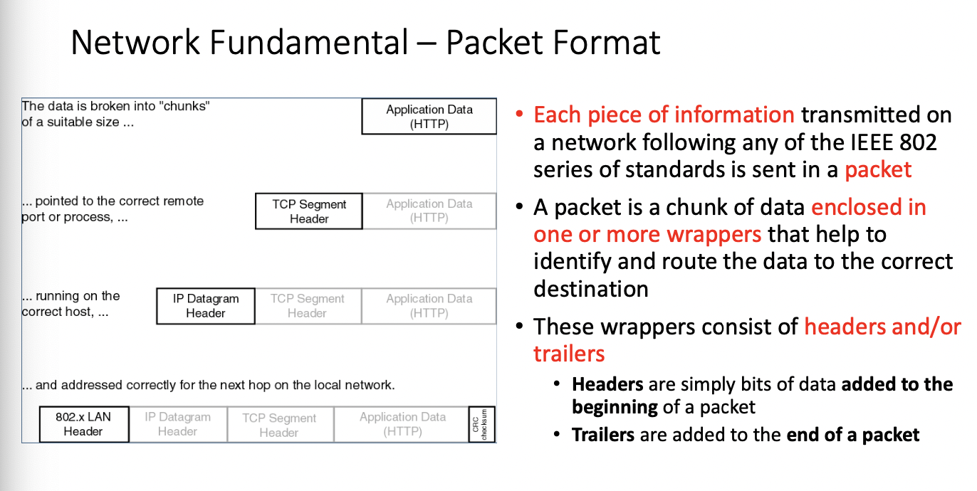
Network Fundamental - Packet Format
- Each piece of info transmitted on a network following any of the IEEE 802 Series of standards is sent in a "packet"
- a packet is a chunk of data enclosed in one of more wrappers that help identify and route the data to the correct destination
- These wrappers consist of headers and or trailers
- headers are simply bits of data added to the beginning of a packet
- trailers are added to the end of a packet
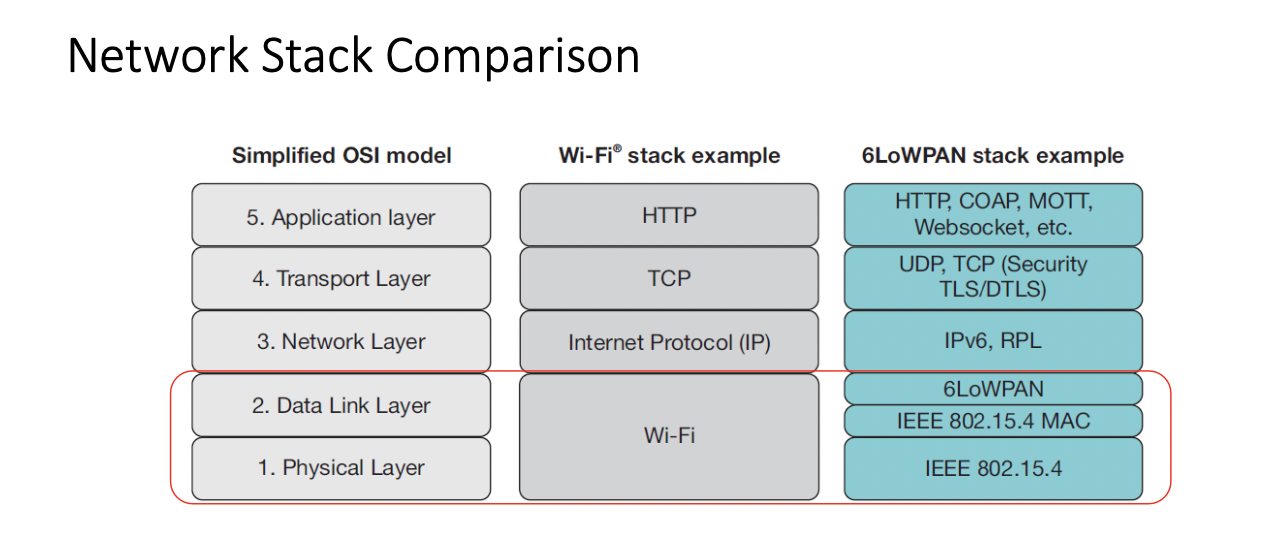
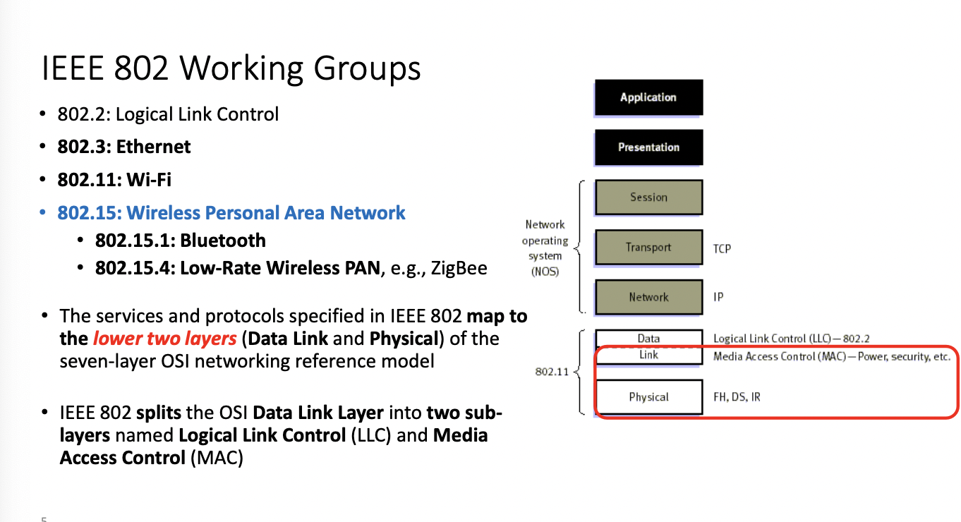
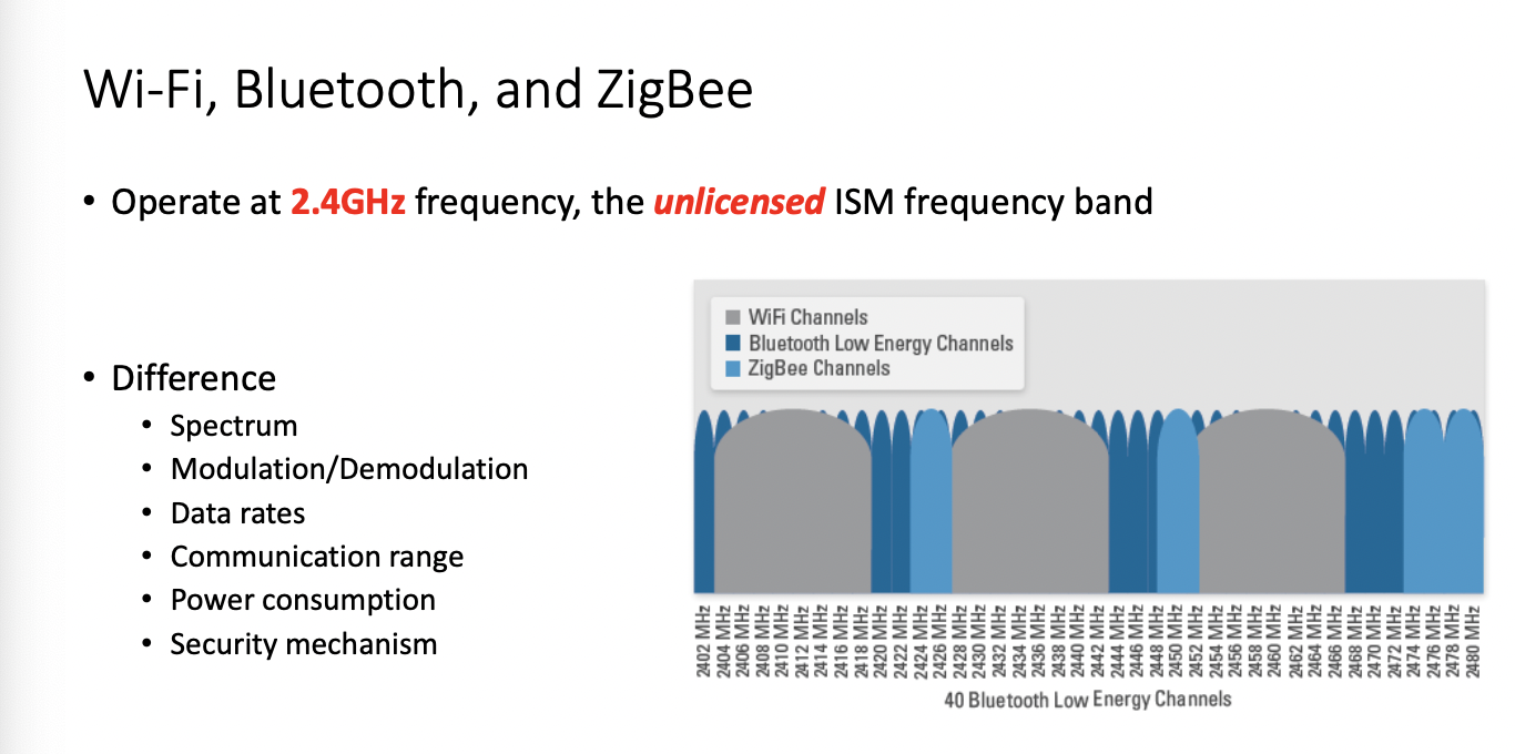

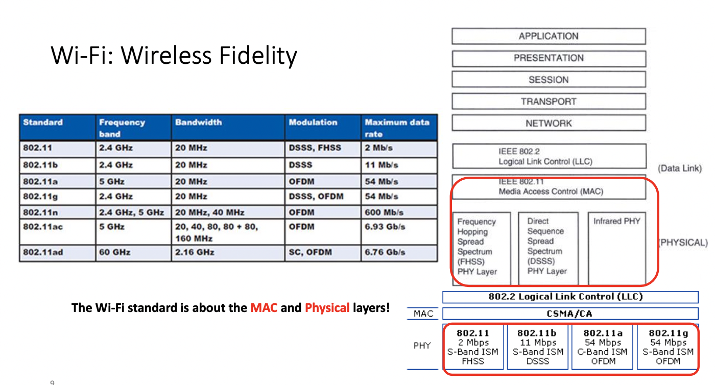
Higher freq, higher throughput, shorter distance
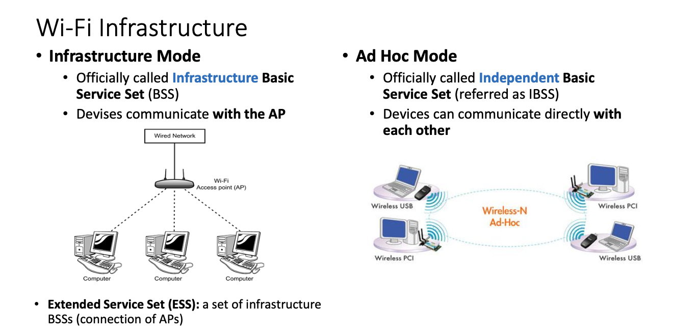
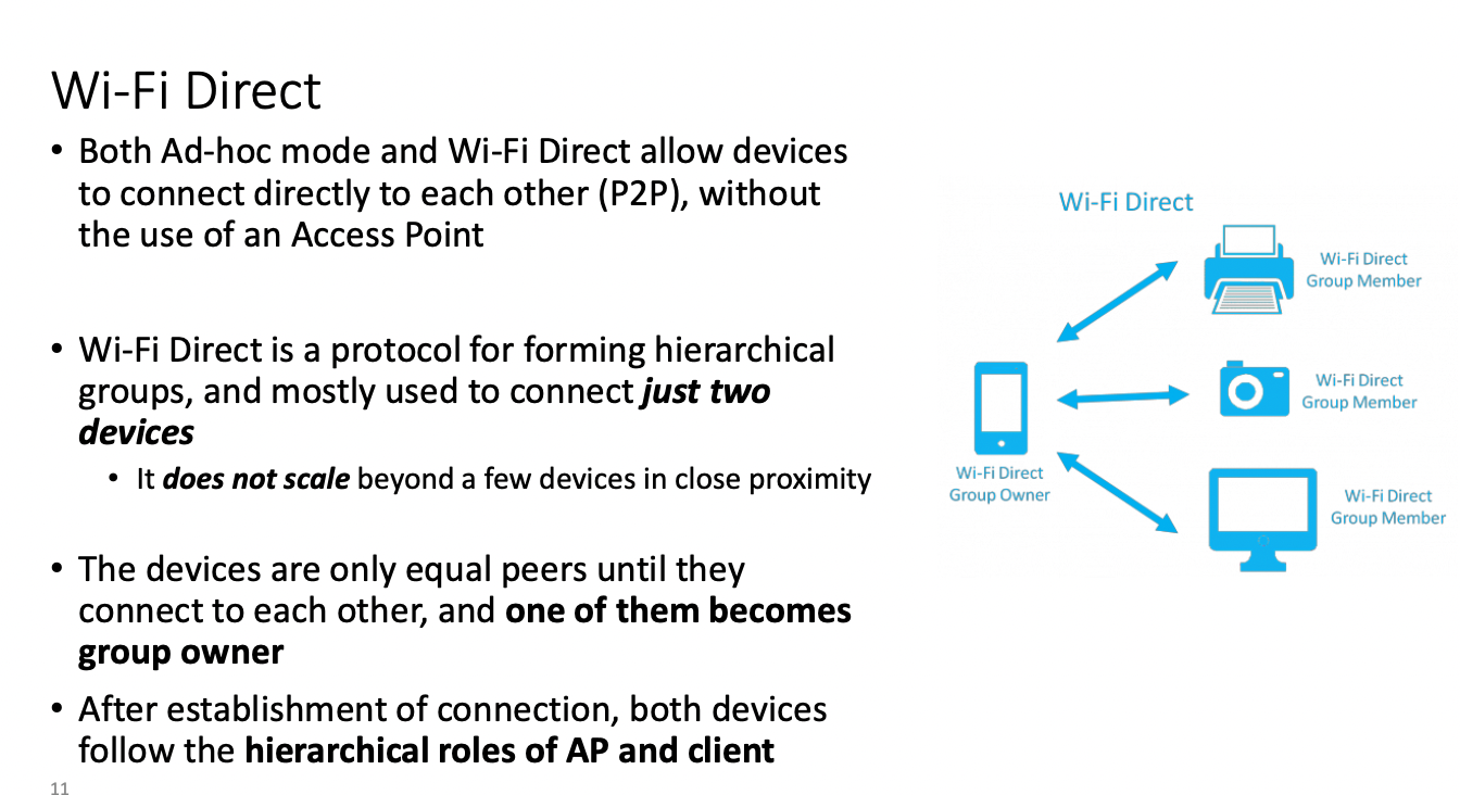
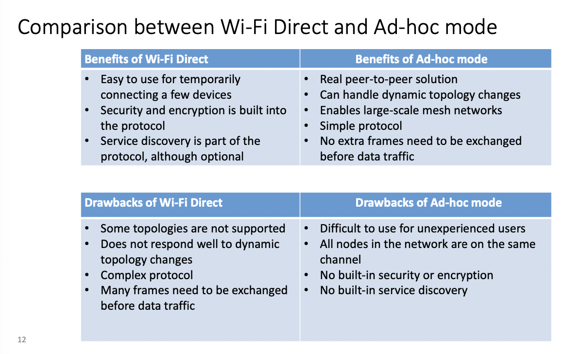
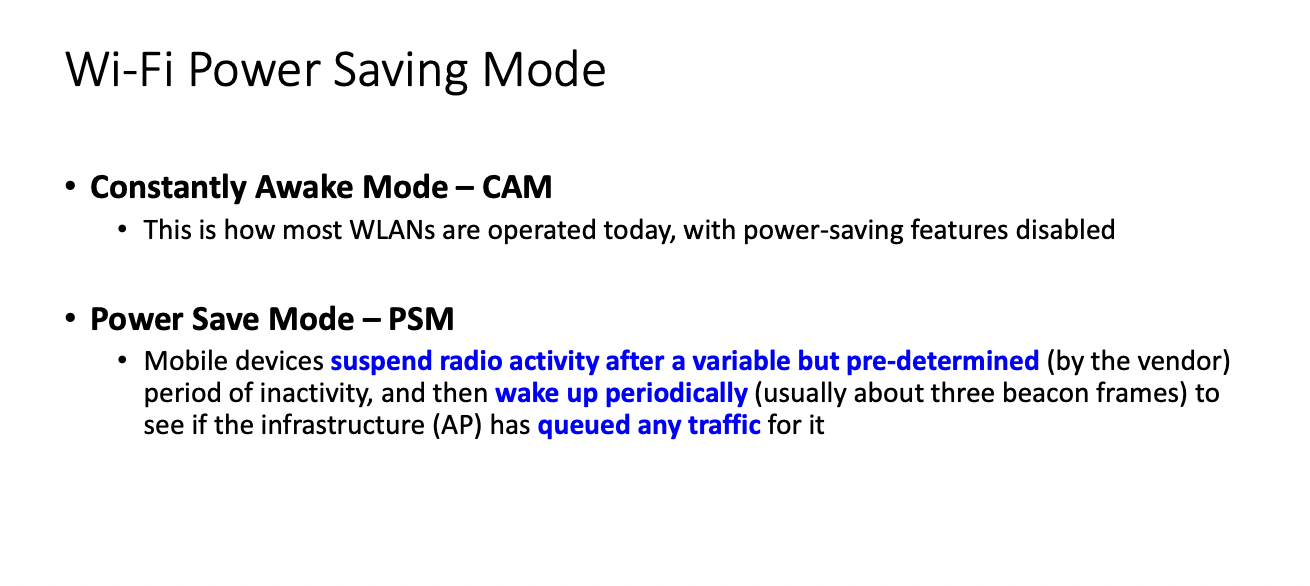
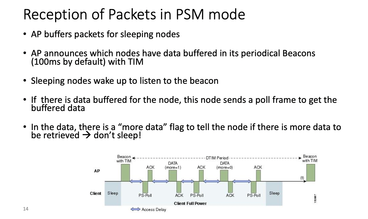
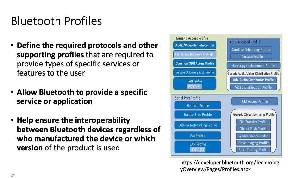
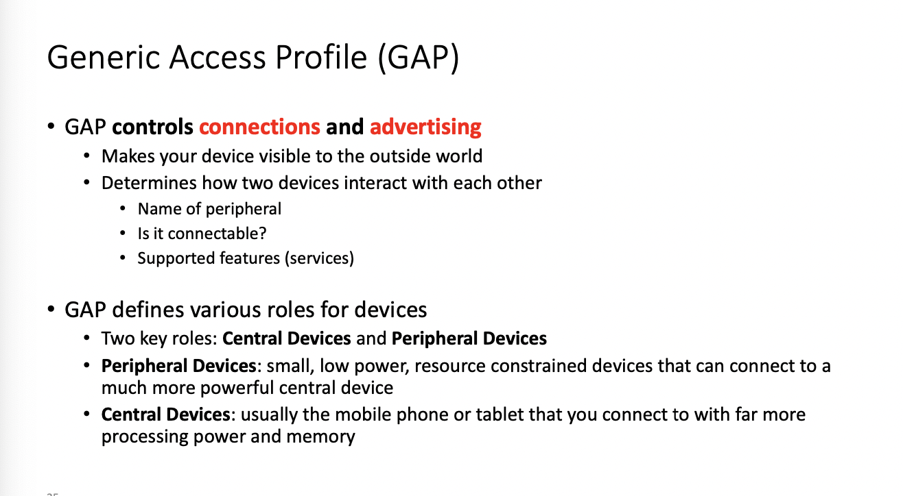
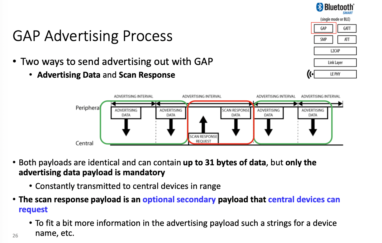
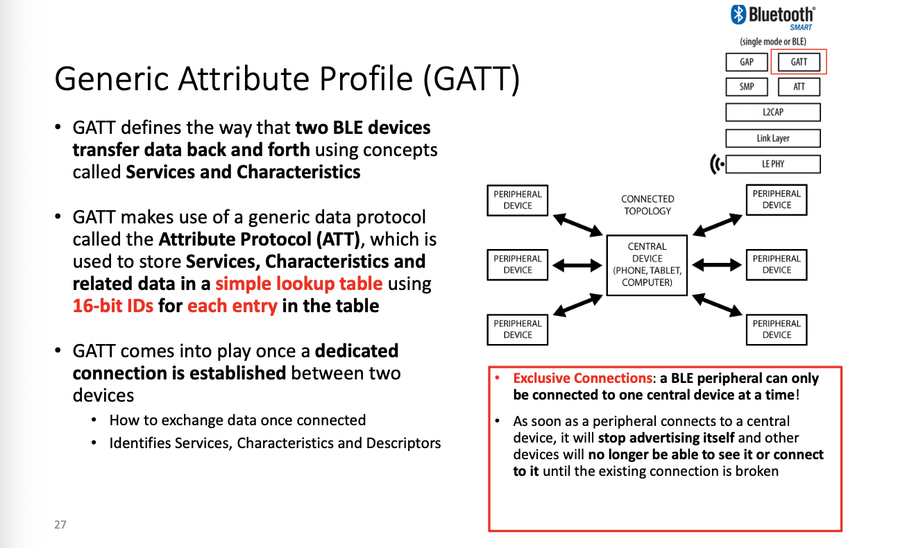
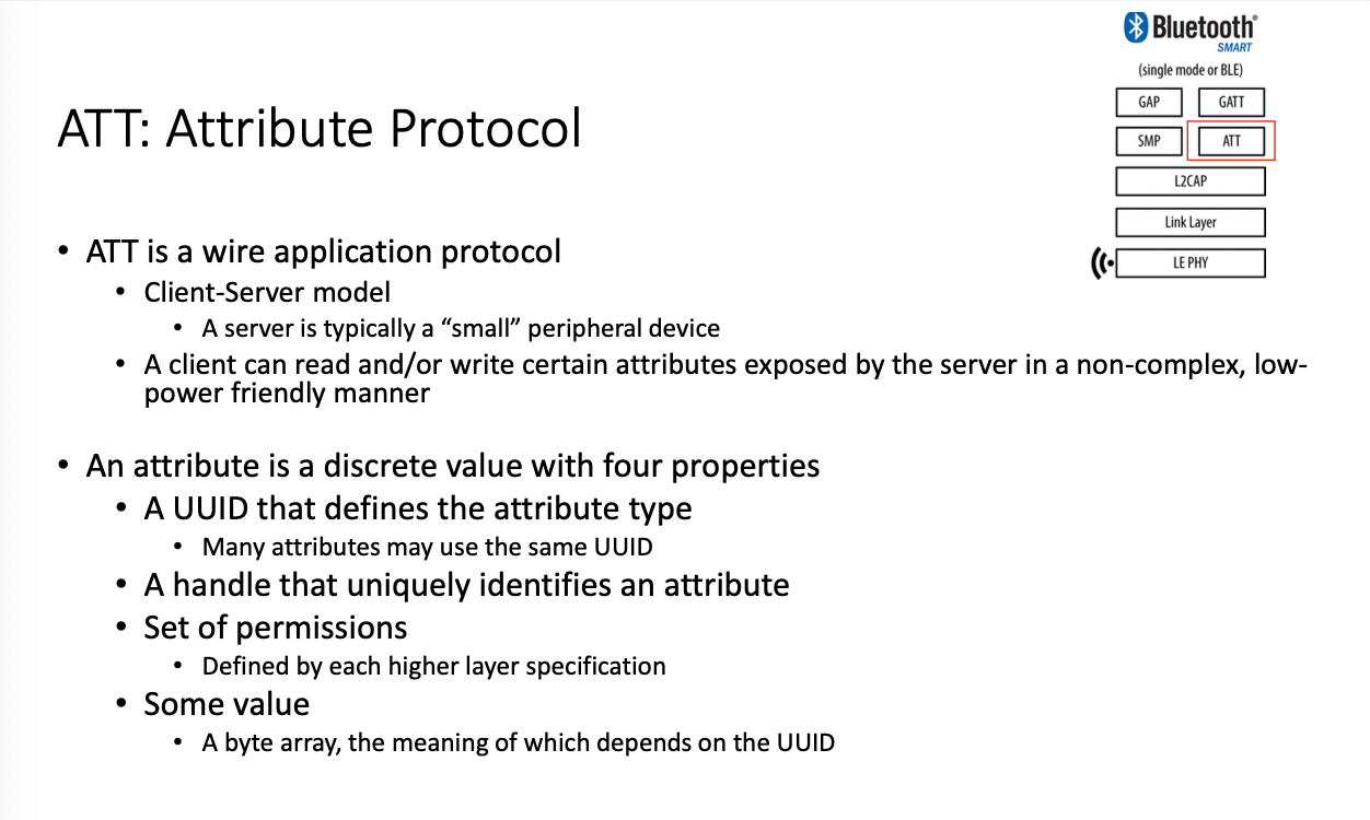
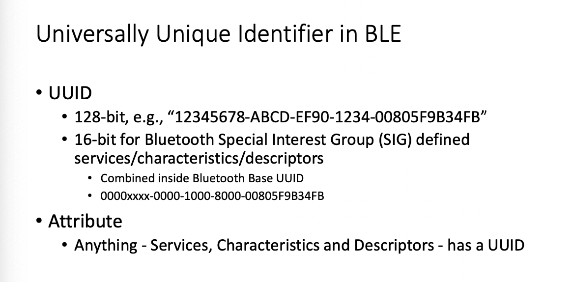
Bluetooth
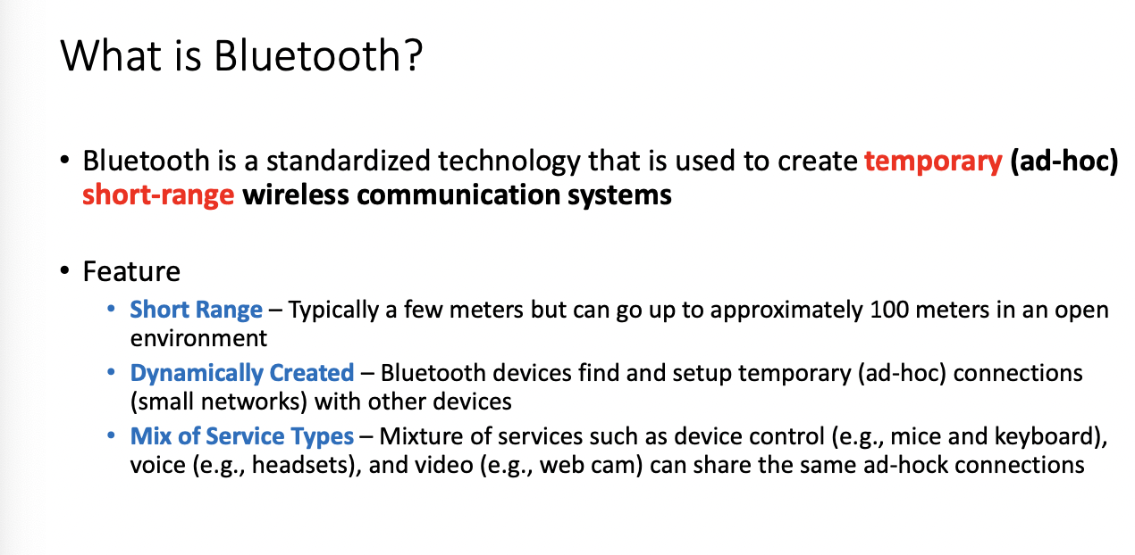
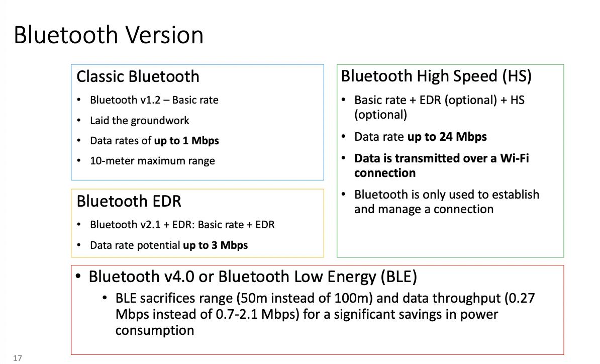
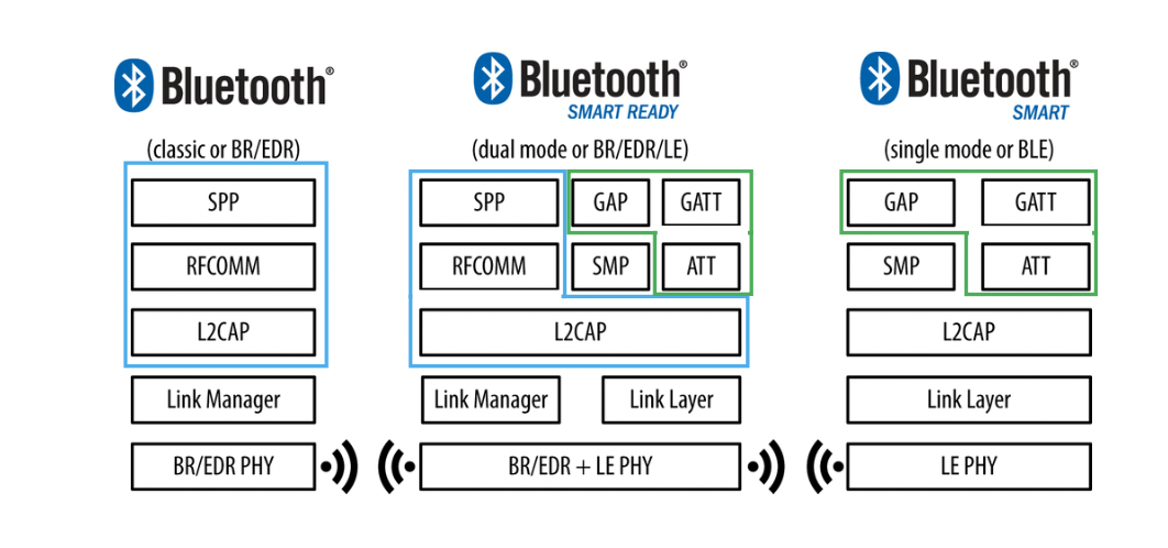
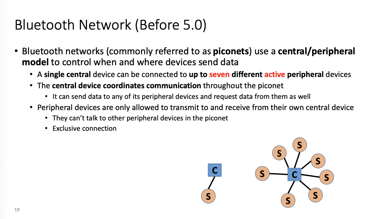
up to seven active peripherals
(hub and peripherals) - piconets
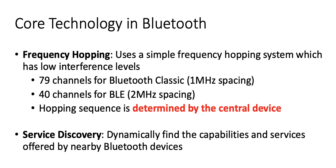
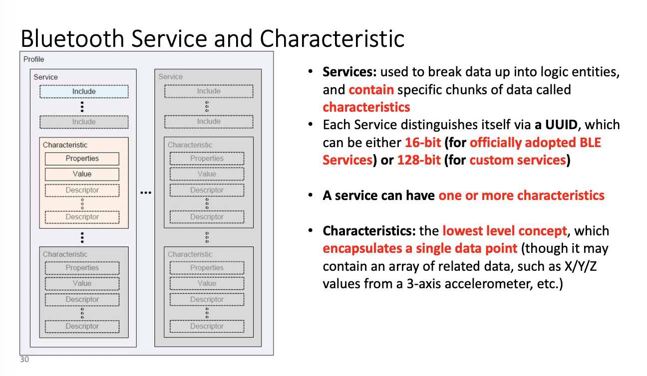
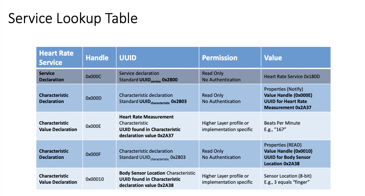
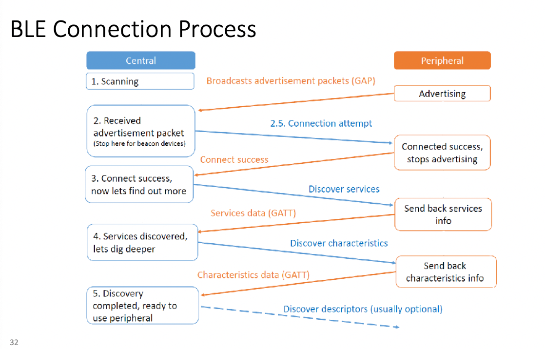
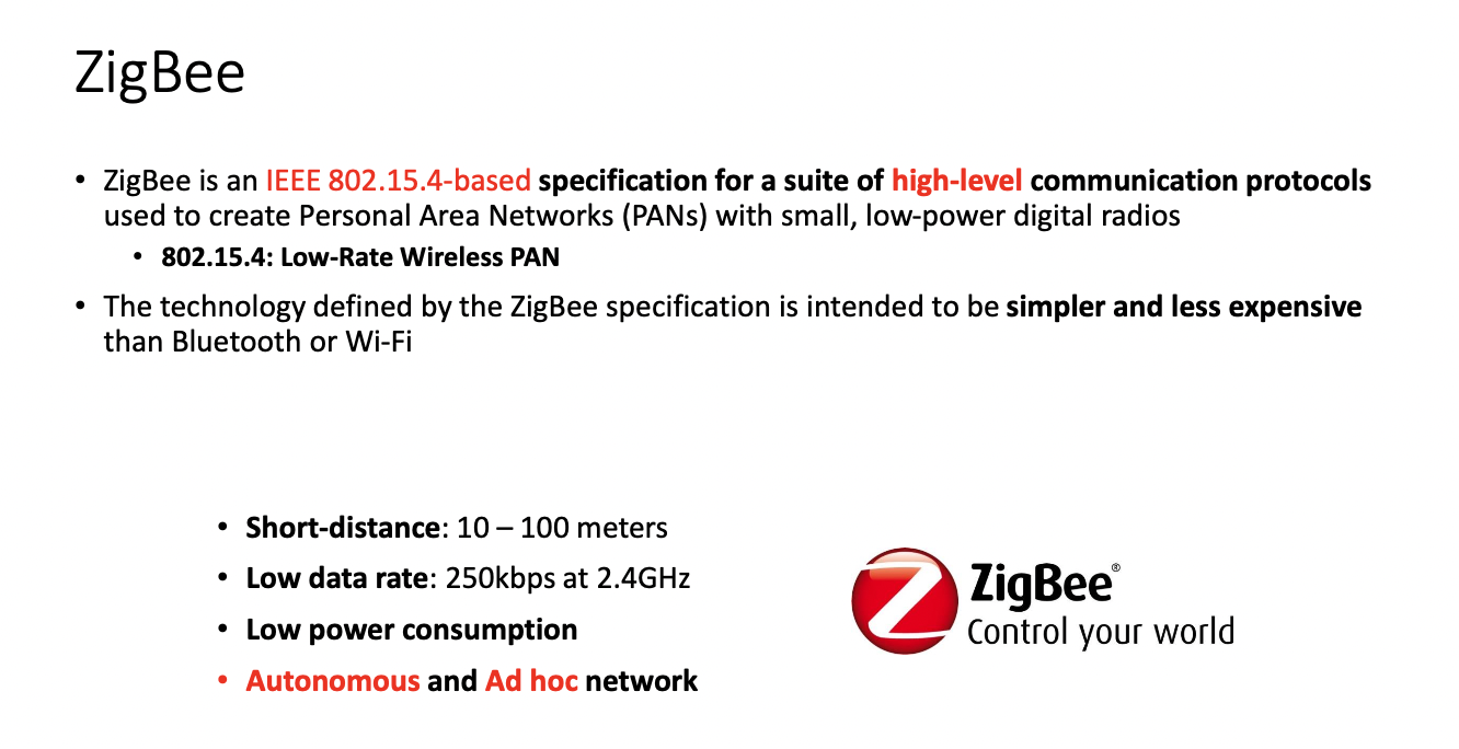
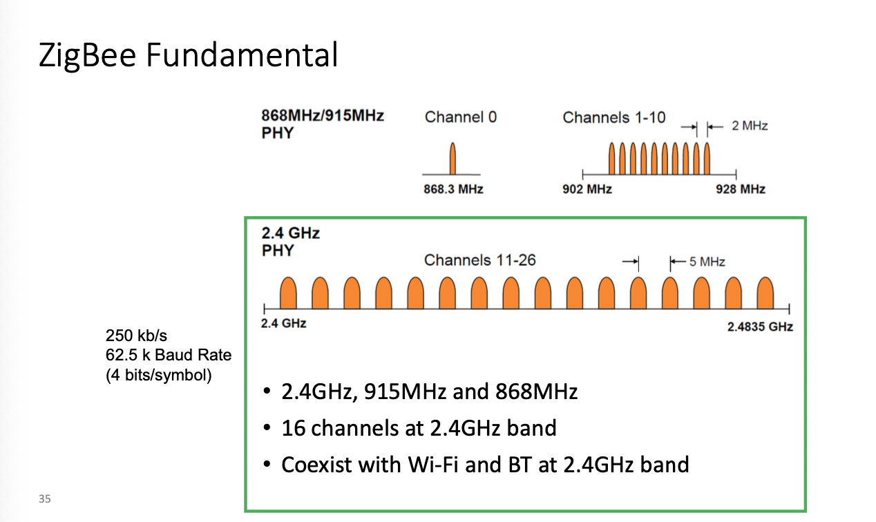
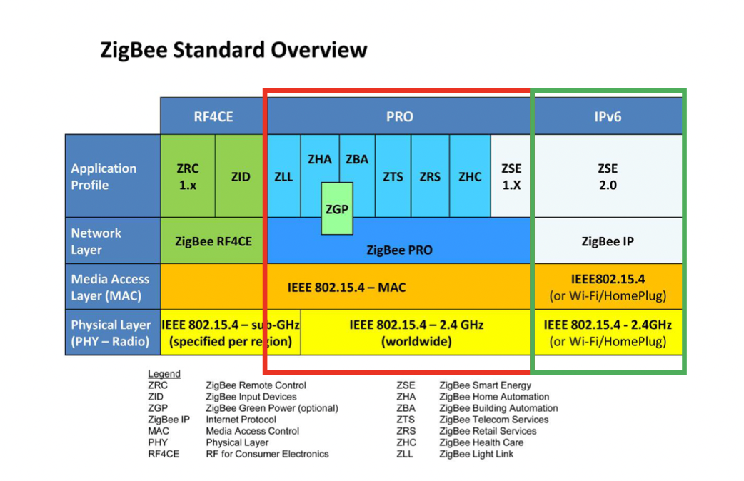
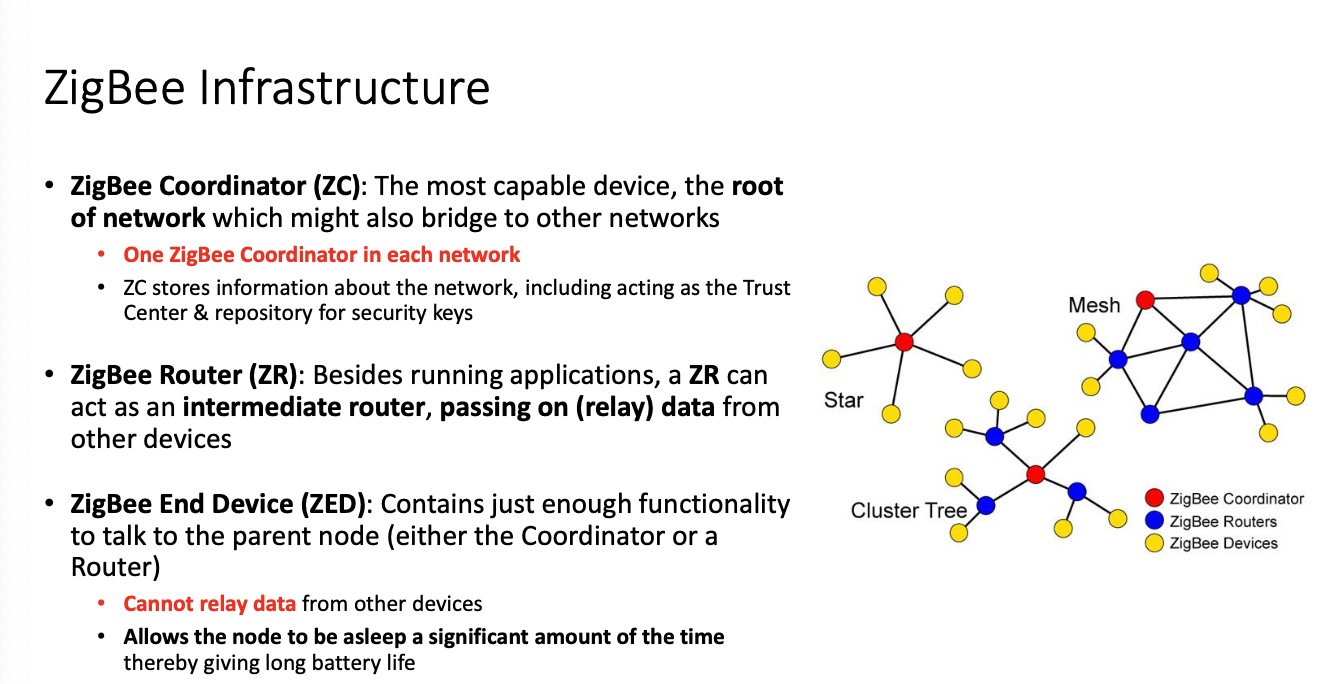
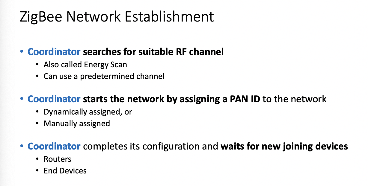
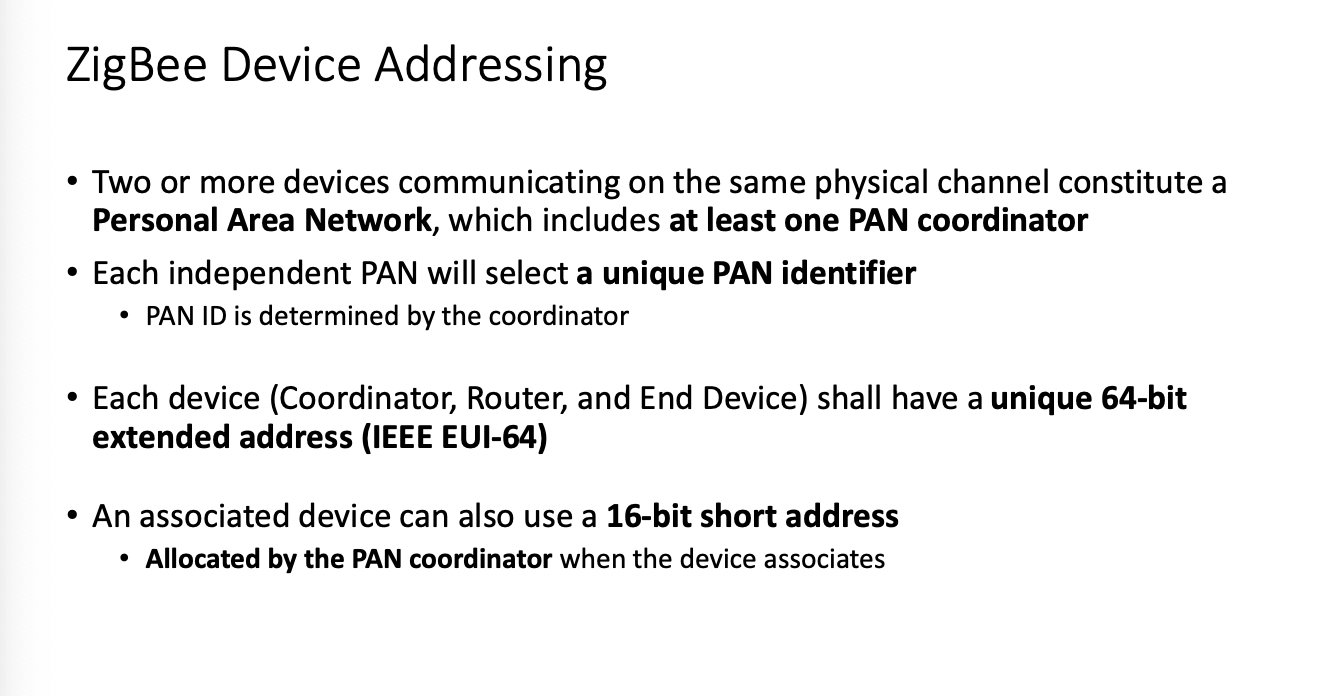
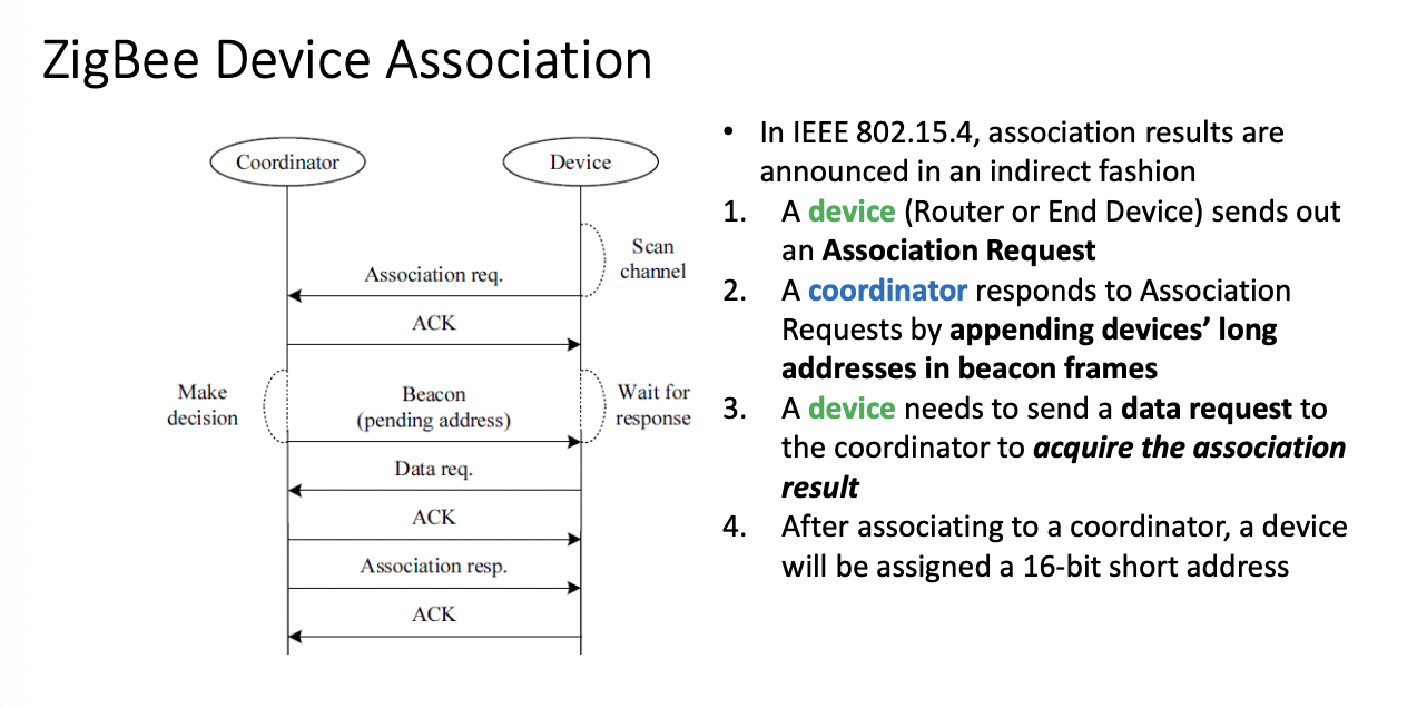
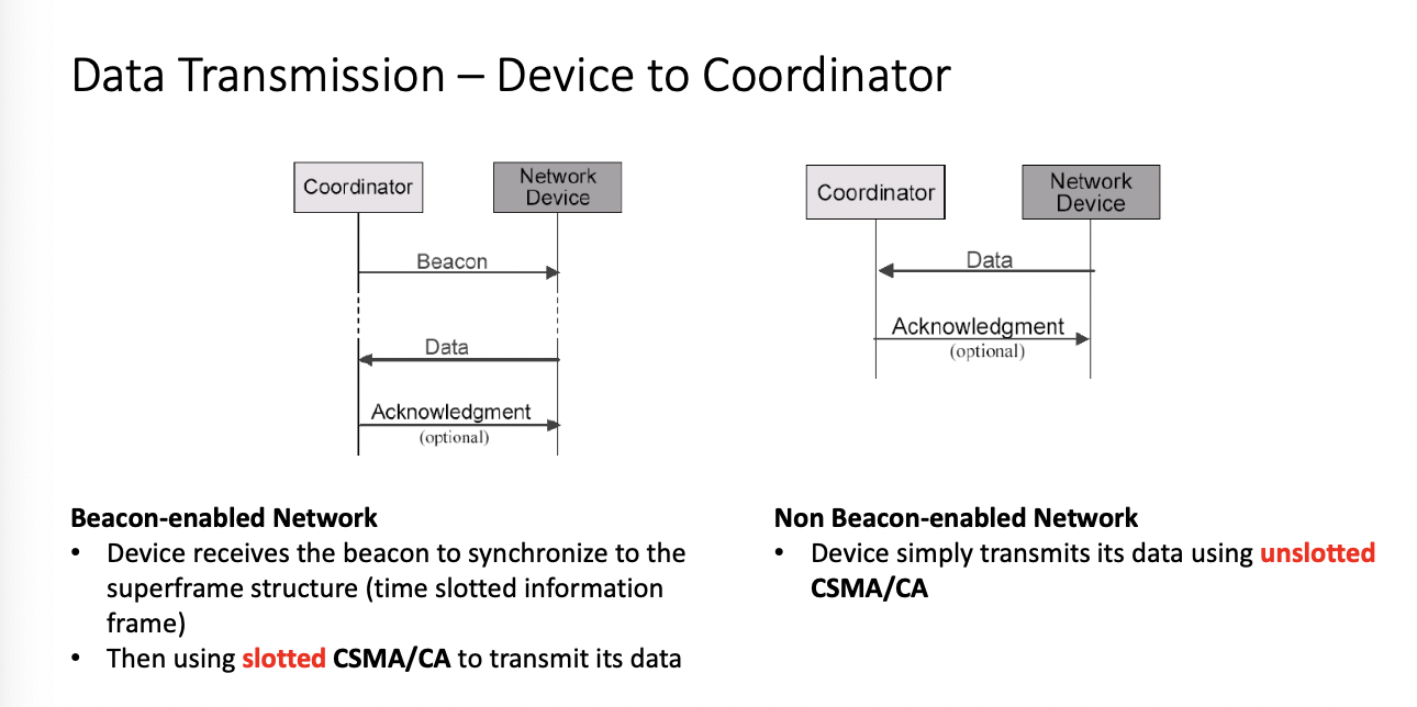
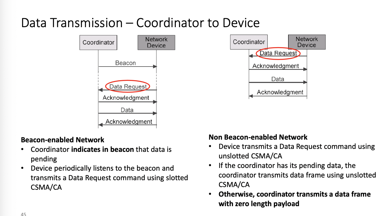
Zigbee
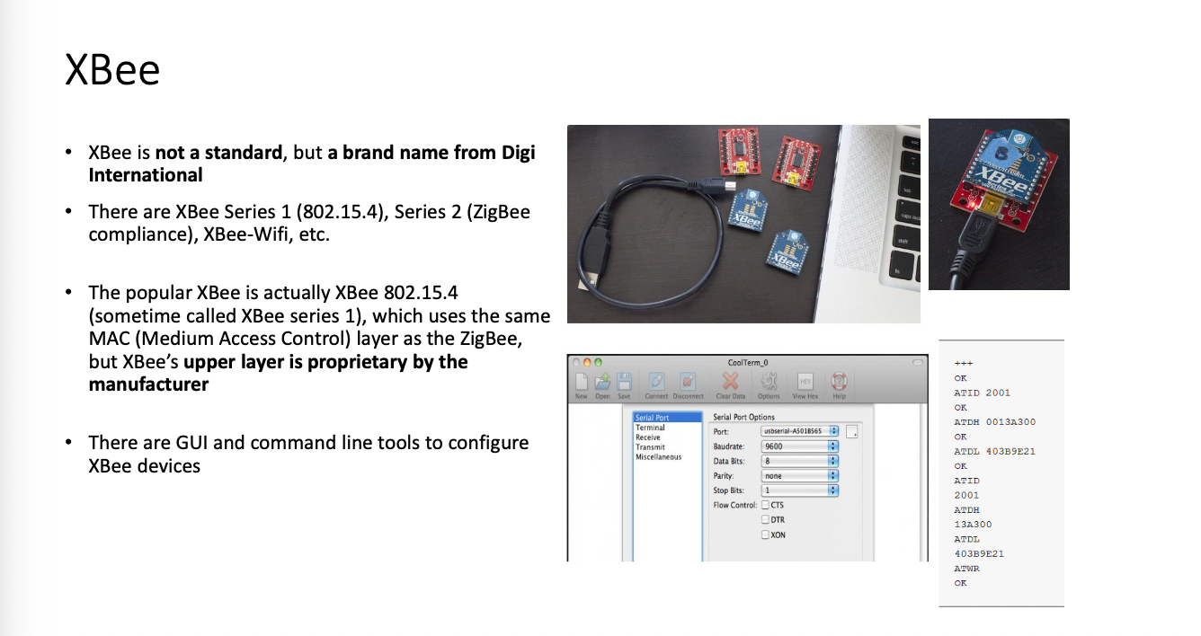
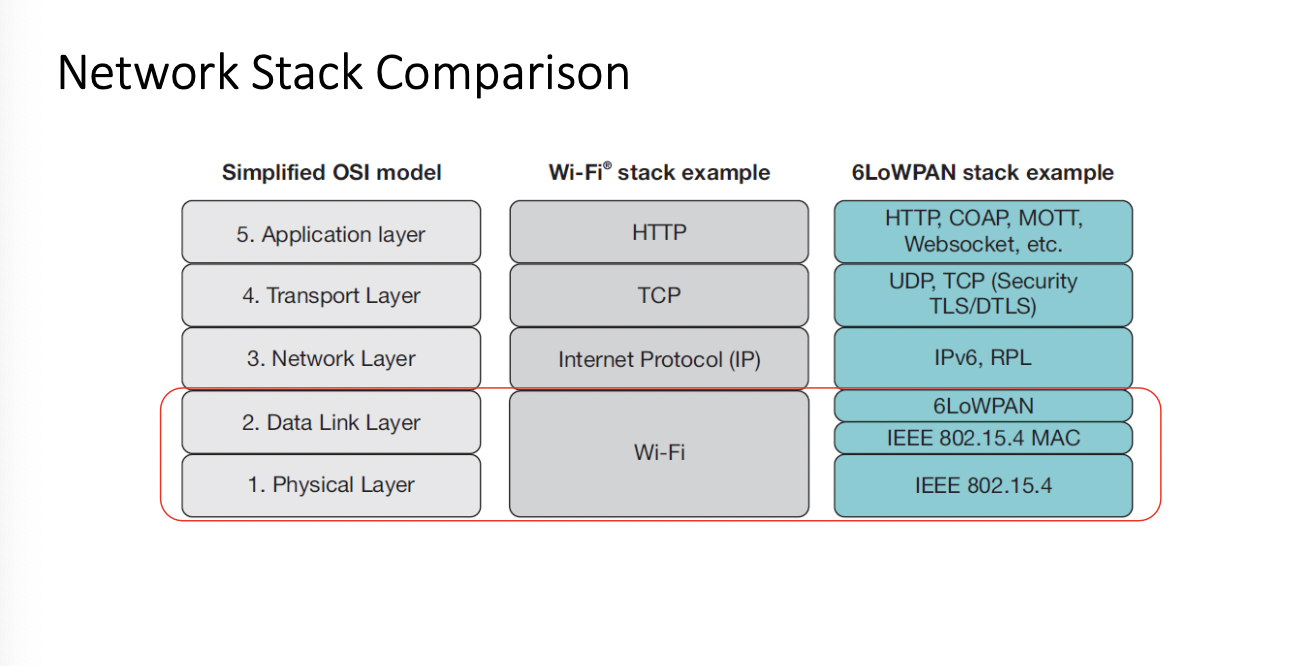
Midterm review
STATIC -
VOLATILE
EXTERN
ADC Resolution is the number of bits
VOLATILE for global variables shared with the ISR.
ISR Short, quick as possible
Don't write debug statement in ISR
ISR Stored in ROM as an entry in an interrupt vector table
Notify OS to process time consuming jobs
- printing etc
Interrupt Priorities
Interrupts 14 points
you may need to disable interrupts during your ISRRoutine()
noInterrupts();
interrupts();
disable all interrupts, not just specific ones
Interrupt latency
- how to calculate
- starting time, ending time - Starting time, when interrupt flag is set
- waiting time, delays for serving higher priority interrupts
- book keeping time
Delay = Starting time +
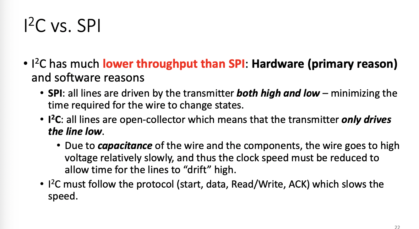
Why is i2c slower? because it needs to use a pullup resistor to drive the signal up or down SPI does this as part of it's protocol
SPI no overhead from data, but overhead from chip select
I2C has more overhead than just the ack signal. you also need address and read/write info
Lab 1 Exercise 5
String input;

int val = 0;


void setup() {

// put your setup code here, to run once:

pinMode(LED_BUILTIN, OUTPUT);

Serial.begin(9600);

}


void loop() {

// put your main code here, to run repeatedly:

if(Serial.available()){

val = digitalRead(LED_BUILTIN);

input = Serial.readString();

Serial.println(input);

//digitalWrite(LED_BUILTIN, val);

if(input == "Toggle"){

toggleLed(val);

}


}


}


int toggleLed(int val){


if(val == 0){

digitalWrite(LED_BUILTIN, HIGH);

}

else{

digitalWrite(LED_BUILTIN, LOW);

}

}
Lab 2 Exercise 3
//Exercise 3 - Rupp

int tempCell = A0;

float tempRead;

float centigrade;

float voltage;

void setup() {

// put your setup code here, to run once:


Serial.begin(9600);

}


void loop() {

// put your main code here, to run repeatedly:

float tempRead = analogRead(tempCell);

centigrade = convertTemp(tempRead);

Serial.println(centigrade);

delay(1000);

}


float convertTemp(int tempRead){

float cent;

voltage = tempRead * 5;

voltage /= 1024;

cent = (voltage -0.5) *100;

return cent;

}
Lab 2 exercise 7
//Exercise 7 - Rupp

int tempCell = A0;

int sensorPin = 2;

int buzzerPin = 7;

float tempRead;

float centigrade;

float voltage;

int userInput;

void setup() {

// put your setup code here, to run once:

pinMode(sensorPin, OUTPUT);

pinMode(LED_BUILTIN, OUTPUT);

pinMode(buzzerPin,OUTPUT);

digitalWrite(buzzerPin, LOW);

digitalWrite(LED_BUILTIN, LOW);

Serial.begin(9600);

}


void loop() {

// put your main code here, to run repeatedly:


if(Serial.available()){

userInput = Serial.parseInt();

}


digitalWrite(sensorPin, HIGH);

tempRead = analogRead(tempCell);


centigrade = convertTemp(tempRead);

if(centigrade > userInput){


sensorBeep();


digitalWrite(LED_BUILTIN, HIGH);

}

else{

digitalWrite(LED_BUILTIN, LOW);

}

Serial.print("Temperature Is ");

Serial.println(centigrade);


}


float convertTemp(int tempRead){

float cent;

voltage = tempRead * 5;

voltage /= 1024;

cent = (voltage - .5) * 100;

return cent;

}


void sensorBeep(){

digitalWrite(buzzerPin, HIGH);

delay(100);

digitalWrite(buzzerPin, LOW);

};
Lab 3 exercise 6
int buttonPin = 2;

int buzzPin = 10;


int previousState = HIGH;

unsigned int previousPress;

volatile int buttonFlag;

int buttonDebounce = 20;

int counter = 0;


void setup()

{

Serial.begin(9600);

pinMode(buzzPin, OUTPUT);

pinMode(buttonPin, INPUT_PULLUP);

attachInterrupt(digitalPinToInterrupt(2), button_ISR, CHANGE);

}


void loop()

{

if((millis() - previousPress) > buttonDebounce && buttonFlag)

{

previousPress = millis();

if(digitalRead(buttonPin) == LOW && previousState == HIGH)

{

digitalWrite(buzzPin, HIGH);

delay(1000);

digitalWrite(buzzPin, LOW);

previousState = LOW;

counter += 1;

Serial.println(counter);

}


else if(digitalRead(buttonPin) == HIGH && previousState == LOW)

{

previousState = HIGH;

}

buttonFlag = 0;

}

}


void button_ISR()

{

buttonFlag = 1;

}
Lab 3 Exercise 3
#include <Keypad.h>


const byte ROWS = 4;

const byte COLS = 4;

char hexKeys[ROWS][COLS] = {

{'1','2','3','A'},

{'4','5','6','B'},

{'7','8','9','C'},

{'*','0','#','D'}

};

const String password = "20174A";

String input;


byte rowPins[ROWS] = {9,8,7,6};

byte colPins[COLS] = {5,4,3,2};


int index = 0;


Keypad myKeypad = Keypad(makeKeymap(hexKeys), rowPins,colPins, ROWS, COLS);

void setup() {

// put your setup code here, to run once:

Serial.begin(9600);

myKeypad.addEventListener(keypadEvent);

myKeypad.setHoldTime(2000);

pinMode(LED_BUILTIN,OUTPUT);


}


void loop() {

// put your main code here, to run repeatedly:

char keyPressed = myKeypad.getKey();

if(keyPressed) {

Serial.println(keyPressed);

if(keyPressed == 'D'){

input="";

}

else{

input += keyPressed;

Serial.println(input);

}

}

//Serial.println(input);

if(input == password){

alarm();

}

}

void alarm(){

Serial.println("ALARM");

digitalWrite(LED_BUILTIN, HIGH);

delay(50);

digitalWrite(LED_BUILTIN, LOW);

}

void keypadEvent(KeypadEvent key){

switch(myKeypad.getState()){

case HOLD:

switch(key){

case 'A':

digitalWrite(LED_BUILTIN, HIGH);

break;

}

case PRESSED:

switch(key){

case 'C':

digitalWrite(LED_BUILTIN, LOW);

break;

}

}

}
Lab 4 exercise 2 mega
#include <SoftwareSerial.h>

#include <Keypad.h>


#define rxPin 10

#define txPin 11

int ack = 0;


const byte ROWS = 4;

const byte COLS = 4;

char hexKeys[ROWS][COLS] = {

{'1','2','3','A'},

{'4','5','6','B'},

{'7','8','9','C'},

{'*','0','#','D'}

};

byte rowPins[ROWS] = {9,8,7,6};

byte colPins[COLS] = {5,4,3,2};


Keypad myKeypad = Keypad(makeKeymap(hexKeys), rowPins,colPins, ROWS, COLS);


SoftwareSerial mySerial = SoftwareSerial(rxPin,txPin);


void setup() {

// put your setup code here, to run once:

mySerial.begin(9600);

Serial.begin(9600);

pinMode(rxPin, INPUT);

pinMode(txPin,OUTPUT);


}


void loop() {

// put your main code here, to run repeatedly:

char keyPressed = myKeypad.getKey();

if(keyPressed) {

mySerial.write(keyPressed);

ack = mySerial.read();

if(ack == 1){

Serial.println("TRANSMISSION ACKNLOWLEDGED");

ack = 0;

}

}

}
Lab4 exercise 2 uno
#include <SoftwareSerial.h>

#define rxPin 11

#define txPin 10

char c;


SoftwareSerial mySerial = SoftwareSerial(rxPin, txPin);


void setup() {

// put your setup code here, to run once:

mySerial.begin(9600);

Serial.begin(9600);

pinMode(rxPin, INPUT);

pinMode(txPin, OUTPUT);


}


void loop() {

// put your main code here, to run repeatedly:

if(mySerial.available()){

c = mySerial.read();

}

mySerial.write(1);

Serial.println(c);

}
Lab 4 exercise 4 Mega
#include <Wire.h>
#include <Keypad.h>

#define ROWS 4

#define COLS 4


volatile bool receiving = false;

volatile int ack;

volatile bool keyPressed = false;

char printKey;


char hexKeys[ROWS][COLS] = {

{'1', '2', '3', 'A'},

{'4', '5', '6', 'B'},

{'7', '8', '9', 'C'},

{'*', '0', '#', 'D'}

};


byte rowPins[ROWS] = {9,8,7,6};

byte colPins[COLS] = {5,4,3,2};


Keypad customKeypad = Keypad(makeKeymap(hexKeys), rowPins, colPins, ROWS, COLS);


void setup() {

// put your setup code here, to run once:

Serial.begin(9600);

Serial.println("Arduino Mega Serial Monitor\n");

Wire.begin();

}


void loop() {

// put your main code here, to run repeatedly:


printKey = customKeypad.waitForKey();

if(printKey){

Serial.print("Key pressed = ");

Serial.println(printKey);

Wire.beginTransmission(8);

Wire.write(printKey);

ack = Wire.endTransmission();

keyPressed = false;


if(ack == 0){

Serial.println("Transmission Acknowledged\n");

switch(printKey){

case '1':

activateAccelerometer();

break;

case '2':

activateMagnetometer();

break;

case '3':

activateBoth();

break;

}

} else Serial.println("Transmission NOT Acknowledged");

}

}


float readFloat() {

byte * b = new byte[8];


Wire.requestFrom(8,8);


while(!Wire.available());

for(int i =0; i <= 8; i++){

//while(!Wire.available());

b[i] = Wire.read();

}

return *((float*) b);

}


void activateAccelerometer(){

while(!keyPressed){

Serial.println("------------------------------------");

Serial.println("ACCELEROMETER READINGS");

Serial.print("X: ");


Serial.print(readFloat());


Serial.print(" ");

Serial.print("Y: ");


Serial.print(readFloat());

Serial.print(" ");

Serial.print("Z: ");


Serial.print(readFloat());

Serial.print(" ");

Serial.println("m/s^2");


Serial.println("\nHold any key to stop\n");


printKey = customKeypad.getKey();

if(printKey){

keyPressed = true;

}


delay(1000);

}

}


void activateMagnetometer(){

while(!keyPressed){

Serial.println("------------------------------------");

Serial.println("MAGNETOMETER READINGS");

Serial.print("X: ");


Serial.print(readFloat());


Serial.print(" ");

Serial.print("Y: ");


Serial.print(readFloat());

Serial.print(" ");

Serial.print("Z: ");


Serial.print(readFloat());

Serial.print(" ");

Serial.println("m/s^2");


Serial.println("\nHold any key to stop\n");


printKey = customKeypad.getKey();

if(printKey){

keyPressed = true;

}


delay(1000);

}

}


void activateBoth(){

while(!keyPressed){

Serial.println("------------------------------------");

Serial.println("ACCELEROMETER READINGS");

Serial.print("X: ");


Serial.print(readFloat());


Serial.print(" ");

Serial.print("Y: ");


Serial.print(readFloat());

Serial.print(" ");

Serial.print("Z: ");


Serial.print(readFloat());

Serial.print(" ");

Serial.println("m/s^2");


Serial.println("MAGNETOMETER READINGS");

Serial.print("X: ");


Serial.print(readFloat());


Serial.print(" ");

Serial.print("Y: ");


Serial.print(readFloat());

Serial.print(" ");

Serial.print("Z: ");


Serial.print(readFloat());

Serial.print(" ");

Serial.println("m/s^2");


Serial.println("\nHold any key to stop\n");


printKey = customKeypad.getKey();

if(printKey){

keyPressed = true;;

}


delay(1000);

}

}
Lab 4 exercise 4 Uno
#include <Adafruit_LSM303_Accel.h>

#include <Adafruit_LSM303DLH_Mag.h>

#include <Adafruit_Sensor.h>

#include <Wire.h>

#include <SoftwareSerial.h>

#define SDA A4

#define SCL A5


volatile char c;

volatile bool receiving = false;

volatile bool newChar = false;

float x,y,z,a,b,d;

int type = 0;

bool both = false;


Adafruit_LSM303DLH_Mag_Unified mag = Adafruit_LSM303DLH_Mag_Unified(12345);

Adafruit_LSM303_Accel_Unified accel = Adafruit_LSM303_Accel_Unified(54321);


void setup() {

// put your setup code here, to run once:


Wire.begin(8);

Wire.onReceive(receiveEvent);

Wire.onRequest(requestEvent);

#ifndef ESP8266

while (!Serial)

; // will pause Zero, Leonardo, etc until serial console opens

#endif


Serial.begin(9600);


Serial.println("Arduino Uno Serial Monitor\n");

Serial.println("Accelerometer Test");

Serial.println("");


/* Initialise the sensor */

if (!accel.begin()) {

/* There was a problem detecting the ADXL345 ... check your connections */

Serial.println("Ooops, no LSM303 detected ... Check your wiring!");

while (1)

;

}


/* Display some basic information on this sensor */

displayAccelSensorDetails();


accel.setRange(LSM303_RANGE_4G);

Serial.print("Range set to: ");

lsm303_accel_range_t new_range = accel.getRange();

switch (new_range) {

case LSM303_RANGE_2G:

Serial.println("+- 2G");

break;

case LSM303_RANGE_4G:

Serial.println("+- 4G");

break;

case LSM303_RANGE_8G:

Serial.println("+- 8G");

break;

case LSM303_RANGE_16G:

Serial.println("+- 16G");

break;

}


accel.setMode(LSM303_MODE_NORMAL);

Serial.print("Mode set to: ");

lsm303_accel_mode_t new_mode = accel.getMode();

switch (new_mode) {

case LSM303_MODE_NORMAL:

Serial.println("Normal");

break;

case LSM303_MODE_LOW_POWER:

Serial.println("Low Power");

break;

case LSM303_MODE_HIGH_RESOLUTION:

Serial.println("High Resolution");

break;

}


Serial.println("");

Serial.println("");

Serial.println("Magnetometer Test");

Serial.println("");


/* Enable auto-gain */

mag.enableAutoRange(true);


/* Initialise the sensor */

if (!mag.begin()) {

/* There was a problem detecting the LSM303 ... check your connections */

Serial.println("Ooops, no LSM303 detected ... Check your wiring!");

while (1)

;

}


/* Display some basic information on this sensor */

displayMagnetoSensorDetails();


Serial.println("Enter 1 to activate accelerometer readings");

Serial.println("Enter 2 to activate magnetometer readings");

Serial.println("Enter 3 to activate both readings");


}


void loop() {

// put your main code here, to run repeatedly:


if(newChar){

newChar = false;

Serial.print("\nReceived character = ");

Serial.println(c);

Serial.println("");

chooseMode(c);

}


}


void receiveEvent(int bytes){

c = Wire.read();

newChar = true;

}


void chooseMode(char c){

switch(c){

case '1':

both = false;

activateAccelerometer();

break;

case '2':

both = false;

activateMagnetometer();

break;

case '3':

both = true;

activeateBoth();

break;

default:

Serial.println("Unsupported Command");

Serial.println("Enter 1, 2, or 3.");

break;

}

}


void activateAccelerometer(){

while(!newChar){

sensors_event_t event;

accel.getEvent(&event);

/* Display the results (acceleration is measured in m/s^2) */

Serial.println("ACCELEROMETER READINGS");

Serial.print("X: ");

Serial.print(event.acceleration.x);

x = event.acceleration.x;

Serial.print(" ");

Serial.print("Y: ");

Serial.print(event.acceleration.y);

y = event.acceleration.y;

Serial.print(" ");

Serial.print("Z: ");

Serial.print(event.acceleration.z);

z = event.acceleration.z;

Serial.print(" ");

Serial.println("m/s^2");

/* Delay before the next sample */

delay(1000);

}

}


void activateMagnetometer(){

while(!newChar){

/* Get a new sensor event */

sensors_event_t event;

mag.getEvent(&event);


Serial.println("MAGNETOMETER READINGS");

/* Display the results (magnetic vector values are in micro-Tesla (uT)) */

Serial.print("X: ");

Serial.print(event.magnetic.x);

x = event.magnetic.x;

Serial.print(" ");

Serial.print("Y: ");

Serial.print(event.magnetic.y);

y = event.magnetic.y;

Serial.print(" ");

Serial.print("Z: ");

Serial.print(event.magnetic.z);

z = event.magnetic.z;

Serial.print(" ");

Serial.println("uT");


/* Delay before the next sample */

delay(1000);

}

}


void activeateBoth(){

while(!newChar){


//--------------activate accelerometer readout-----------------------

sensors_event_t event;

accel.getEvent(&event);

/* Display the results (acceleration is measured in m/s^2) */

Serial.println("ACCELEROMETER READINGS");

Serial.print("X: ");

Serial.print(event.acceleration.x);

x = event.acceleration.x;

Serial.print(" ");

Serial.print("Y: ");

Serial.print(event.acceleration.y);

y = event.acceleration.y;

Serial.print(" ");

Serial.print("Z: ");

Serial.print(event.acceleration.z);

z = event.acceleration.z;

Serial.print(" ");

Serial.println("m/s^2");


//--------------activate magnetometer readout-----------------------

mag.getEvent(&event);


Serial.println("MAGNETOMETER READINGS");

/* Display the results (magnetic vector values are in micro-Tesla (uT)) */

Serial.print("X: ");

Serial.print(event.magnetic.x);

a = event.magnetic.x;

Serial.print(" ");

Serial.print("Y: ");

Serial.print(event.magnetic.y);

b = event.magnetic.y;

Serial.print(" ");

Serial.print("Z: ");

Serial.print(event.magnetic.z);

d = event.magnetic.z;

Serial.print(" ");

Serial.println("uT");


delay(1000);

}

}


void displayAccelSensorDetails(void) {

sensor_t sensor;

accel.getSensor(&sensor);

Serial.println("------------------------------------");

Serial.print("Sensor: ");

Serial.println(sensor.name);

Serial.print("Driver Ver: ");

Serial.println(sensor.version);

Serial.print("Unique ID: ");

Serial.println(sensor.sensor_id);

Serial.print("Max Value: ");

Serial.print(sensor.max_value);

Serial.println(" m/s^2");

Serial.print("Min Value: ");

Serial.print(sensor.min_value);

Serial.println(" m/s^2");

Serial.print("Resolution: ");

Serial.print(sensor.resolution);

Serial.println(" m/s^2");

Serial.println("------------------------------------");

Serial.println("");

}


void displayMagnetoSensorDetails(void) {

sensor_t sensor;

mag.getSensor(&sensor);

Serial.println("------------------------------------");

Serial.print("Sensor: ");

Serial.println(sensor.name);

Serial.print("Driver Ver: ");

Serial.println(sensor.version);

Serial.print("Unique ID: ");

Serial.println(sensor.sensor_id);

Serial.print("Max Value: ");

Serial.print(sensor.max_value);

Serial.println(" uT");

Serial.print("Min Value: ");

Serial.print(sensor.min_value);

Serial.println(" uT");

Serial.print("Resolution: ");

Serial.print(sensor.resolution);

Serial.println(" uT");

Serial.println("------------------------------------");

Serial.println("");

}


void requestEvent(){

byte *b;


if((both == false) && (type == 3)){

type = 0;

}

else if((both == true) && (type == 6)){

type = 0;

}

if(type == 0){

b = (byte*) &x;

}

else if(type == 1){

b = (byte*) &y;

}else if(type == 2){

b = (byte*) &z;

}else if(type == 3){

b = (byte*) &a;

}else if(type == 4){

b = (byte*) &b;

}

else if(type == 5){

b = (byte*) &d;

}

for(int i =0;i<=8;i++){

Wire.write(b[i]);

}


type++;

}
Software Architectures for Embedded System
How much control do you need for system response?
Round Robin With Interrupts
Give a scenario you want to move forward final q
main loop polls flags
worst case latency
all isr plus task code
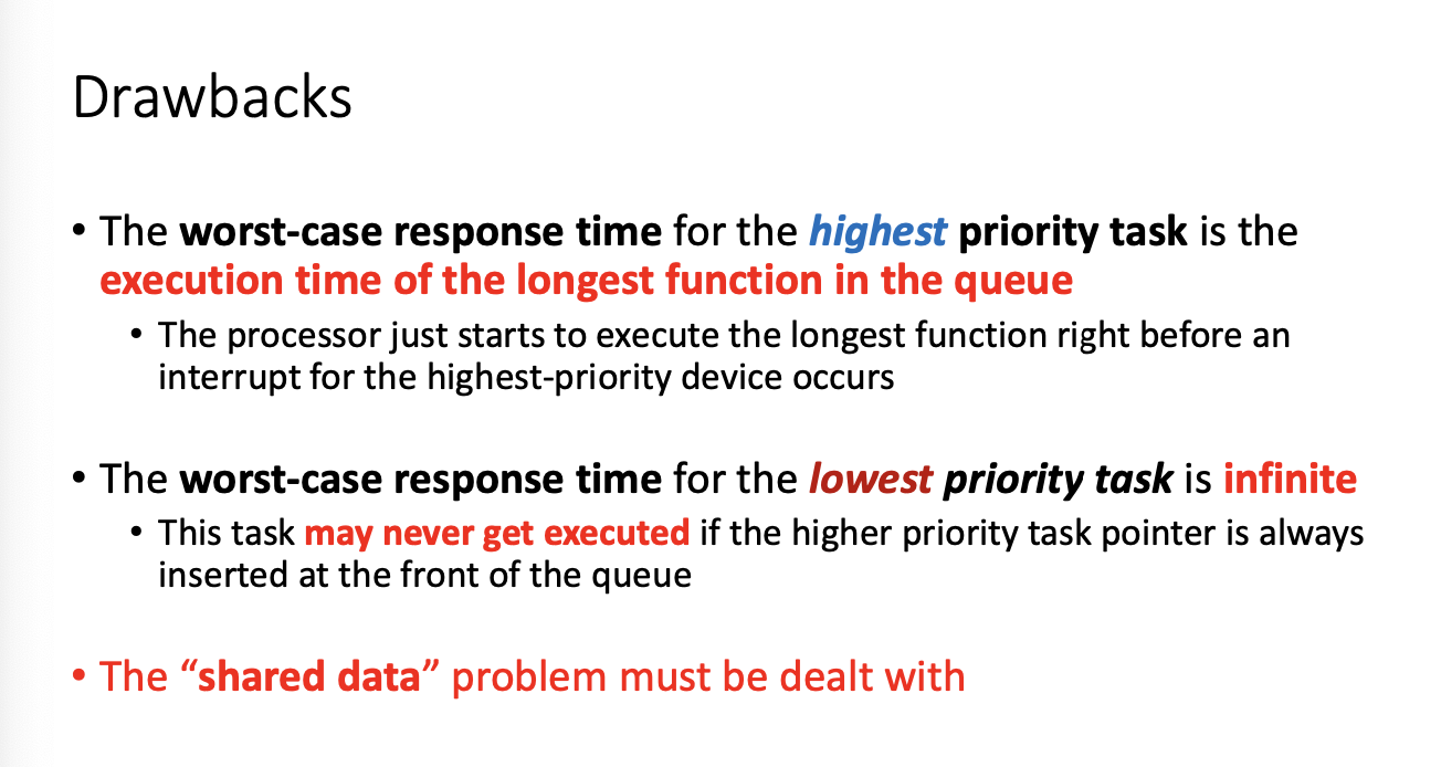
Shared data problem is the biggest issue
CHECK THESE FOR ASSIGNMENT

RTOS is basically a priority queue
Rtos Fundamental Elements
Task and ISR are two fundamental elements in RTOS
- majority of RTOS code resides within task and SIR
- majority of software issues come from task, ISR, or interactions between them
- shared data problem still exists
Tasks are scheduled by RTOS scheduler
ISRs triggered by hardware interrupts
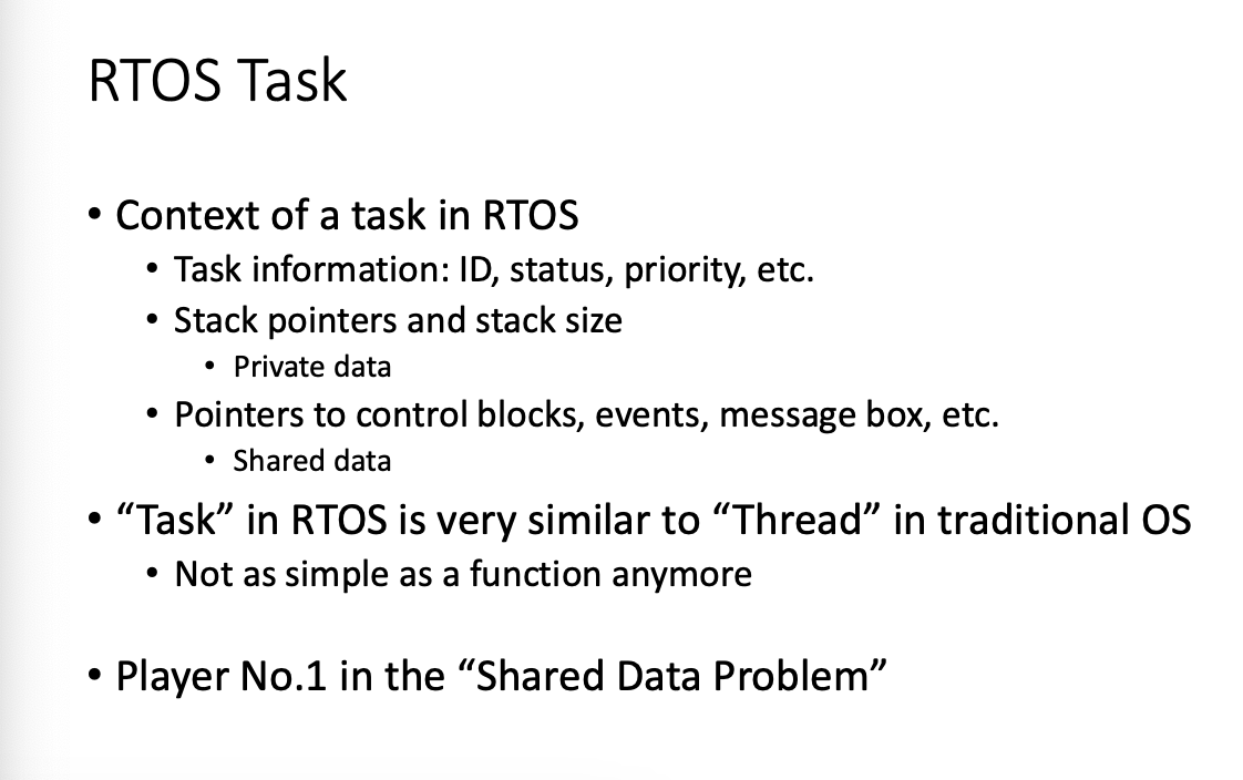
Each task should operate on it's own stack
functions share same stack
task it's data is in it's own stack
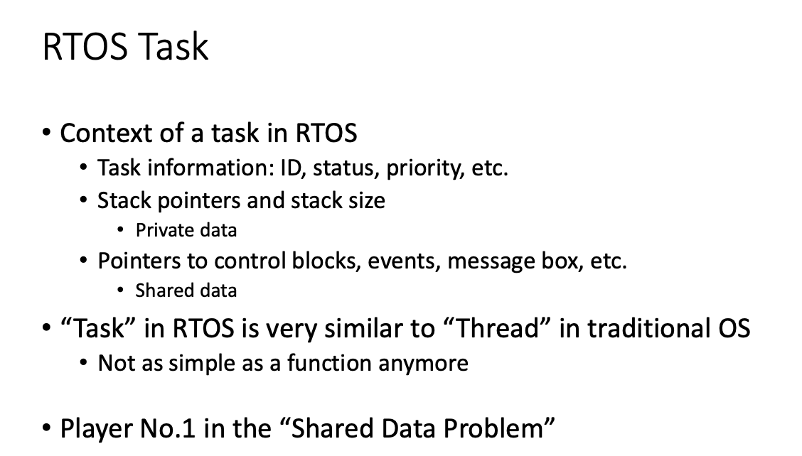
Tasks
you must define reentrant functions
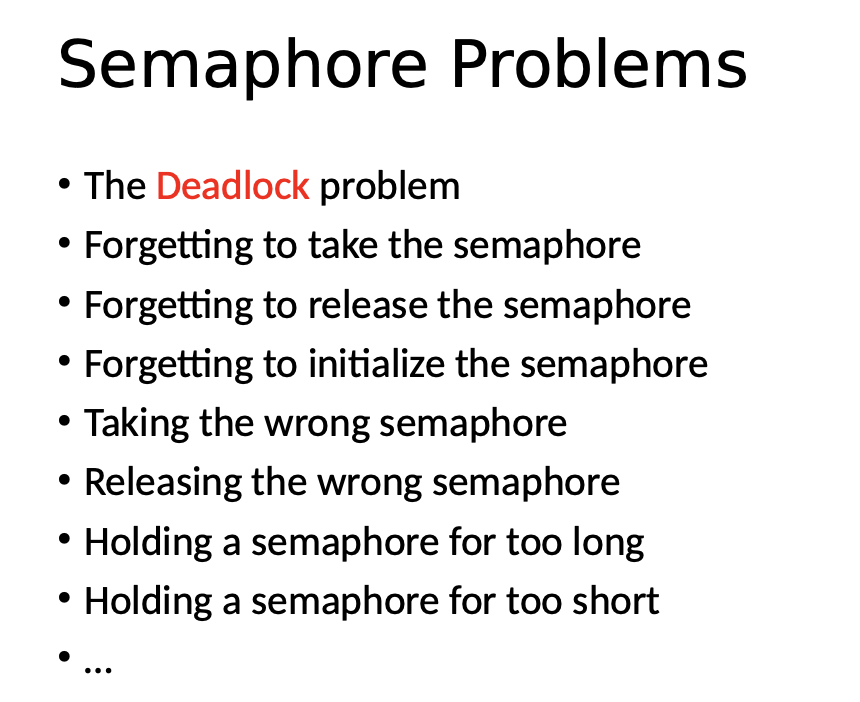
Semaphore terms
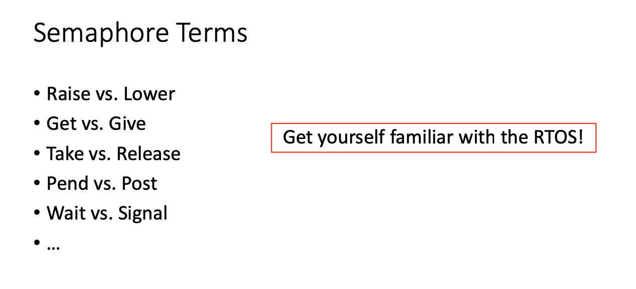
don't put a lot of code between semaphores
Semaphore has it's own queue
DON'T TAKE SEMAPHORE INSIDE INTERRUPTS
You can set global flag if in interrupt to prevent issues
you should avoid using global variables in RTOS
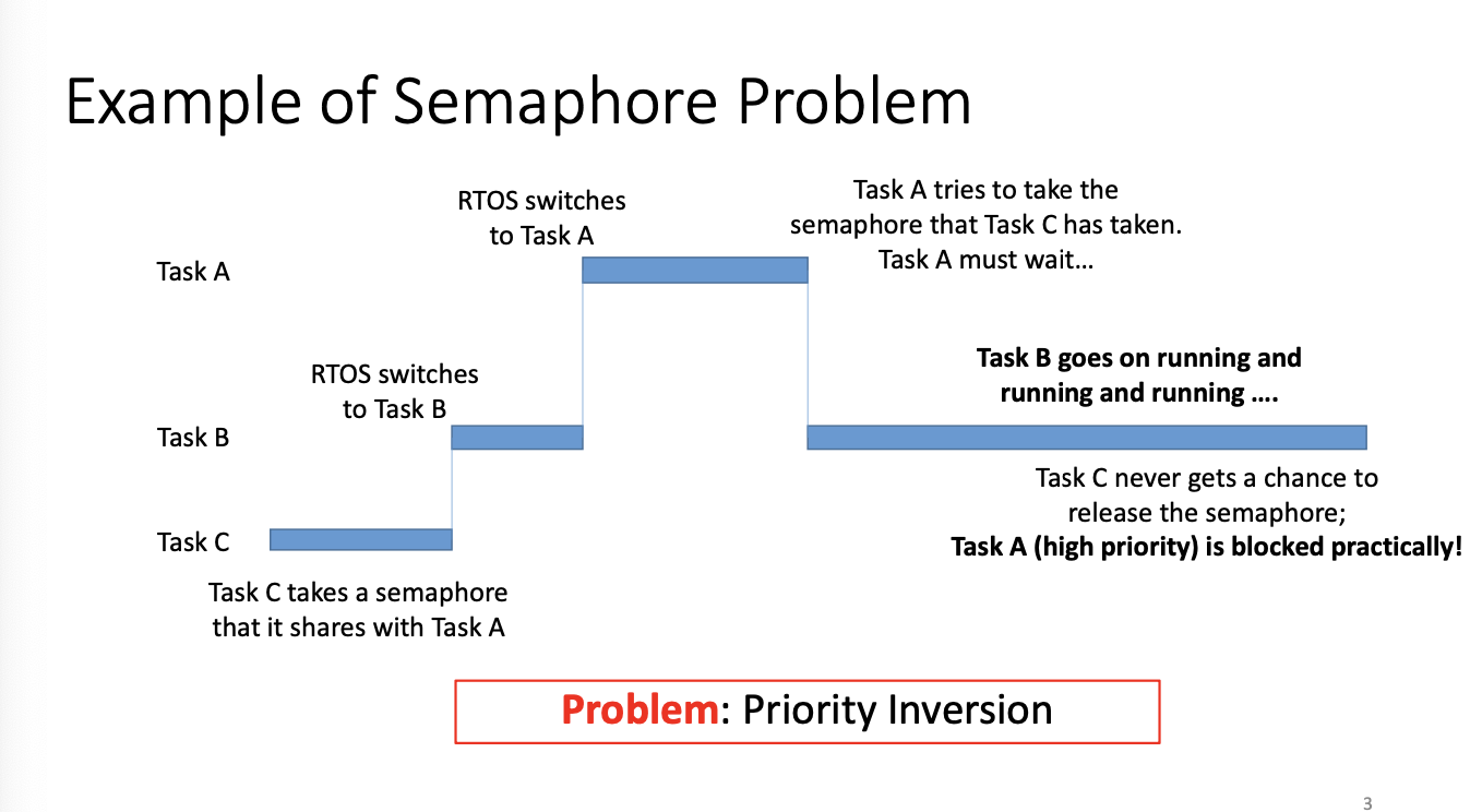
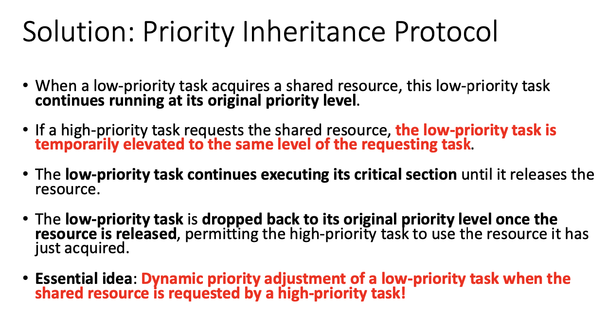
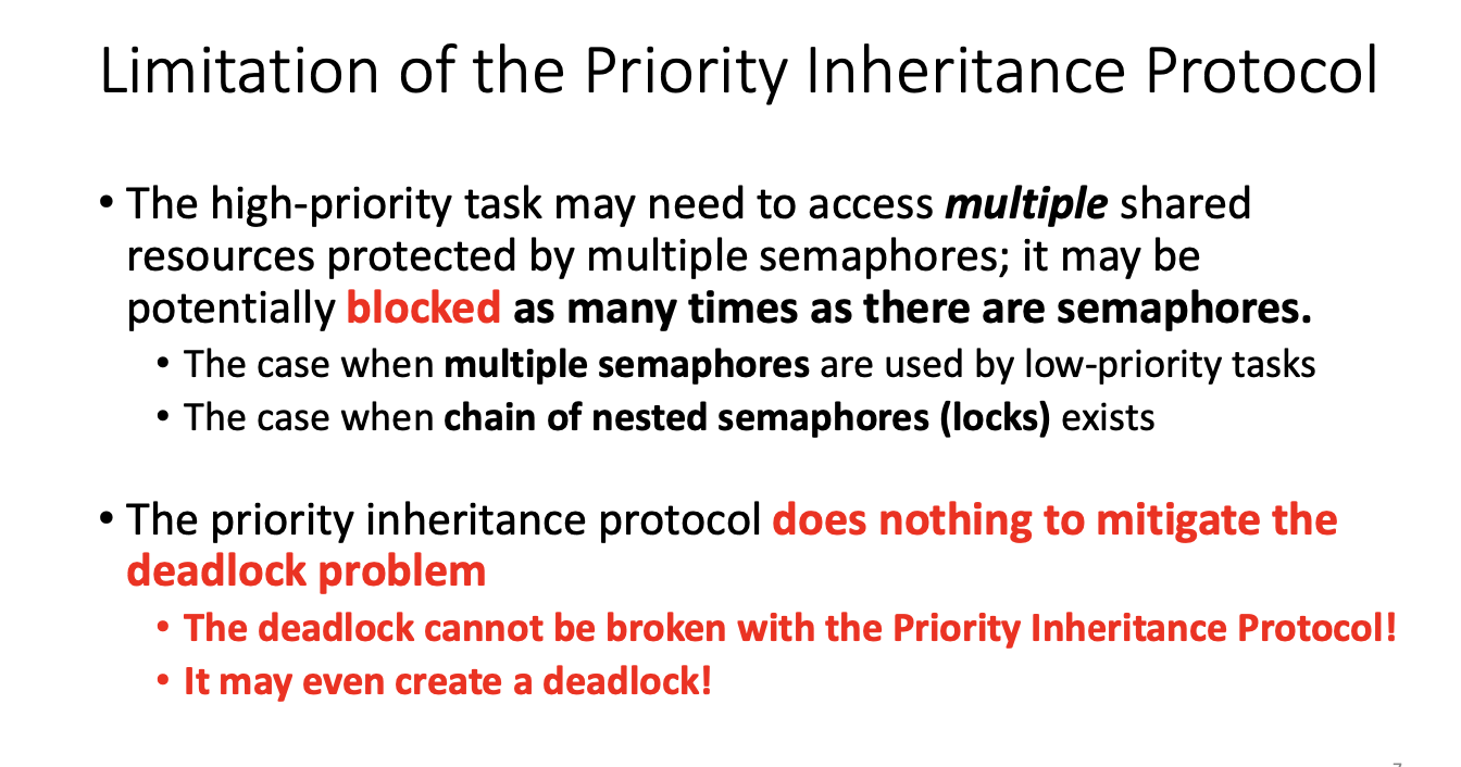
Priority Inheritance Protocol
Inter Task Communication
Semaphores are not considered a communication method
However, we have some other shared data mechanisms in RTOS
ECB event control block
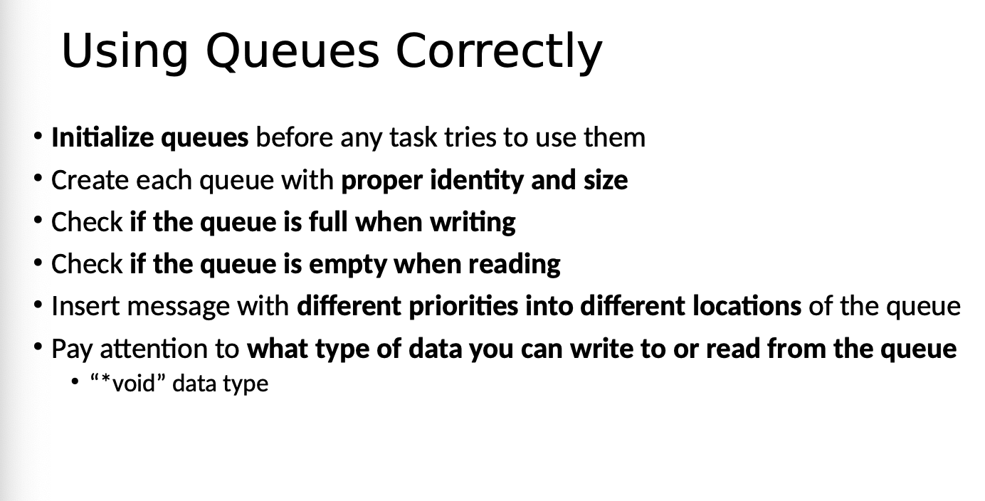
Queues
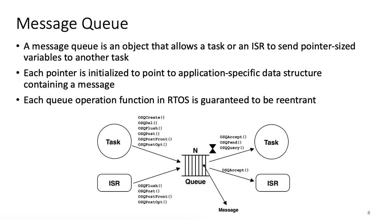
microC os is fifo queue
Queues allow you to get rid of the shared data problem
Mailboxes
A mailbox is essentially queue with a size of 1 and has 1 pointer
If you have to define your own global variable, use semaphore or mutex
Otherwise, use mailbox or queue
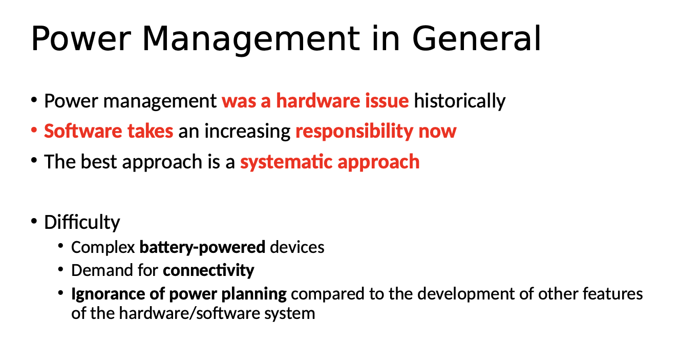
Power Management
Embedded System Bootstrap
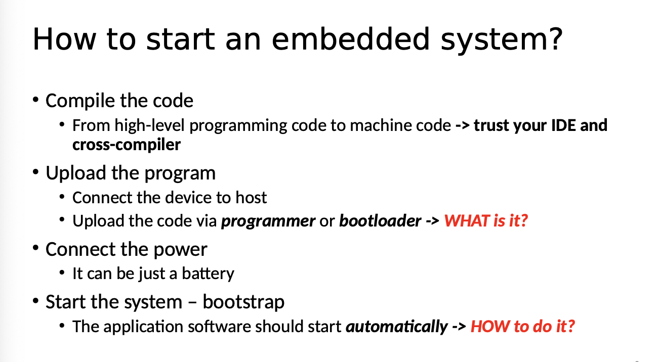
The programmer will check that all code is placed via UART parity bit
The bootloader needs to enable some hardware resources
The bootloader will be triggered with a certain combination of signals
Fuse bytes allow you to lock/unlock boot section, application section or entire rom space
Connected Embedded Systems
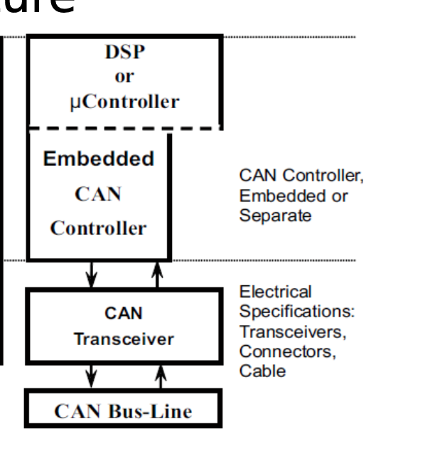
Canbus is a Serial Communication Protocol
Use a bus when you might want to add more later
Limitations, two devices talking at the same time, which is addressed by
CSMA/BA Carrier Sense Multiple access With Bitwise Arbitration
Data messages are transmitted from any node - broadcast
Before broadcast, check bus to see if anything going on
If nothing is there, (driven up and down) recessive status
Collision detection for wired
collision avoidance for wireless
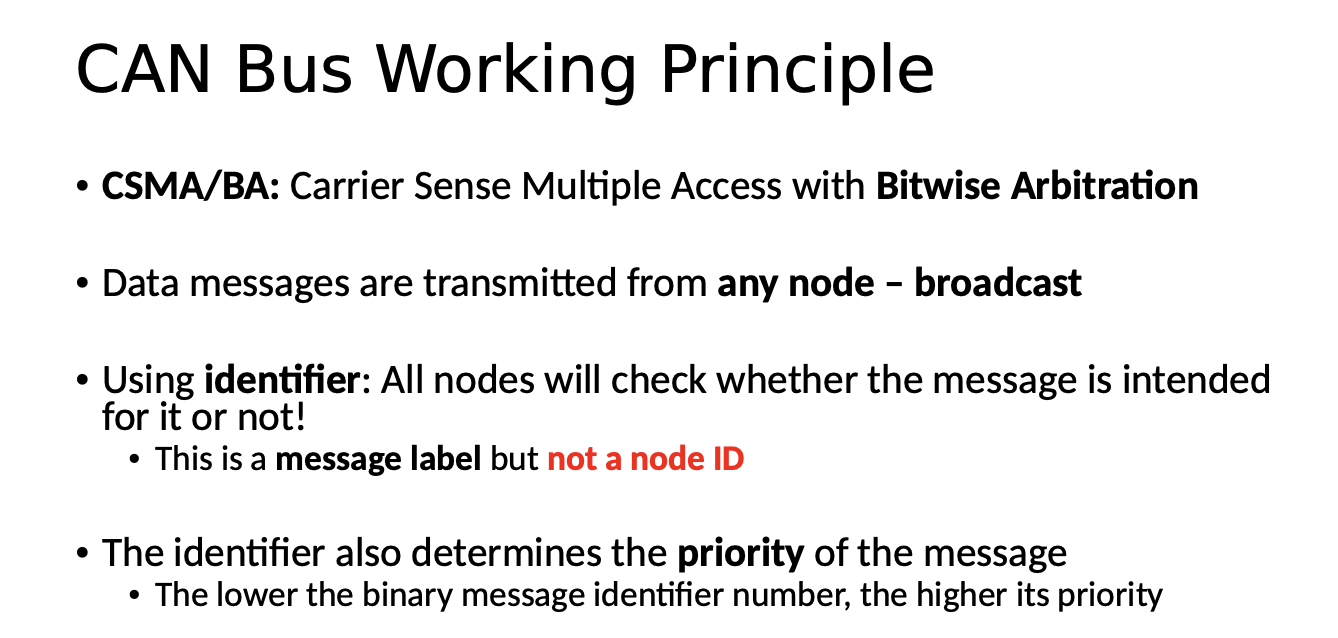
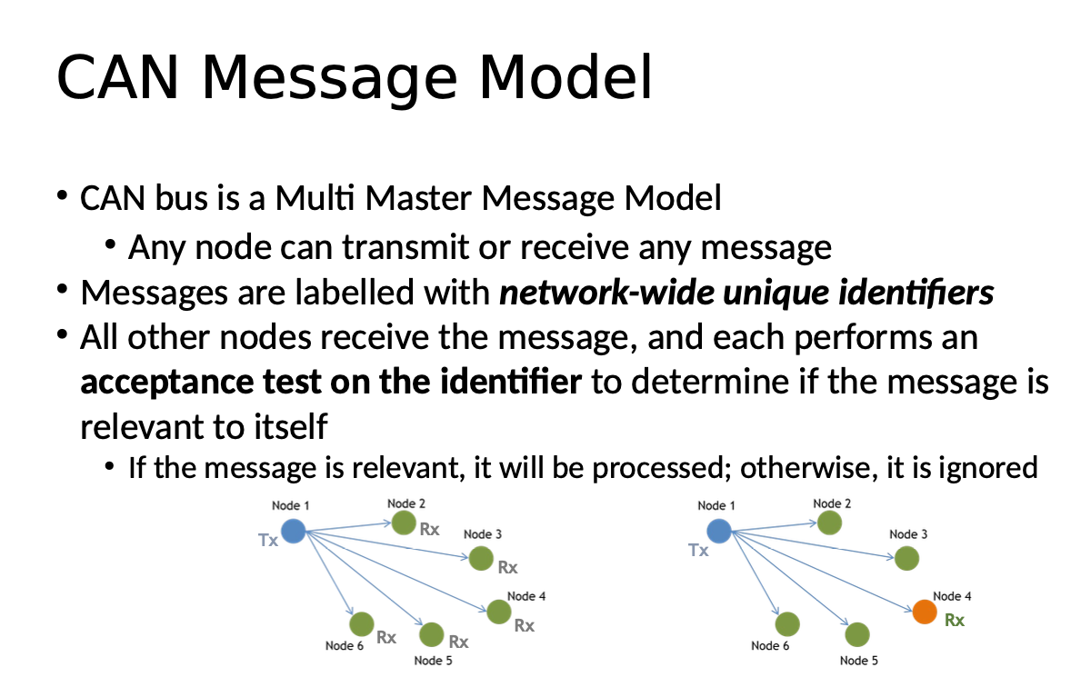
Message id used to identify type of message and help resolve competition
CSMA senses channel for idle
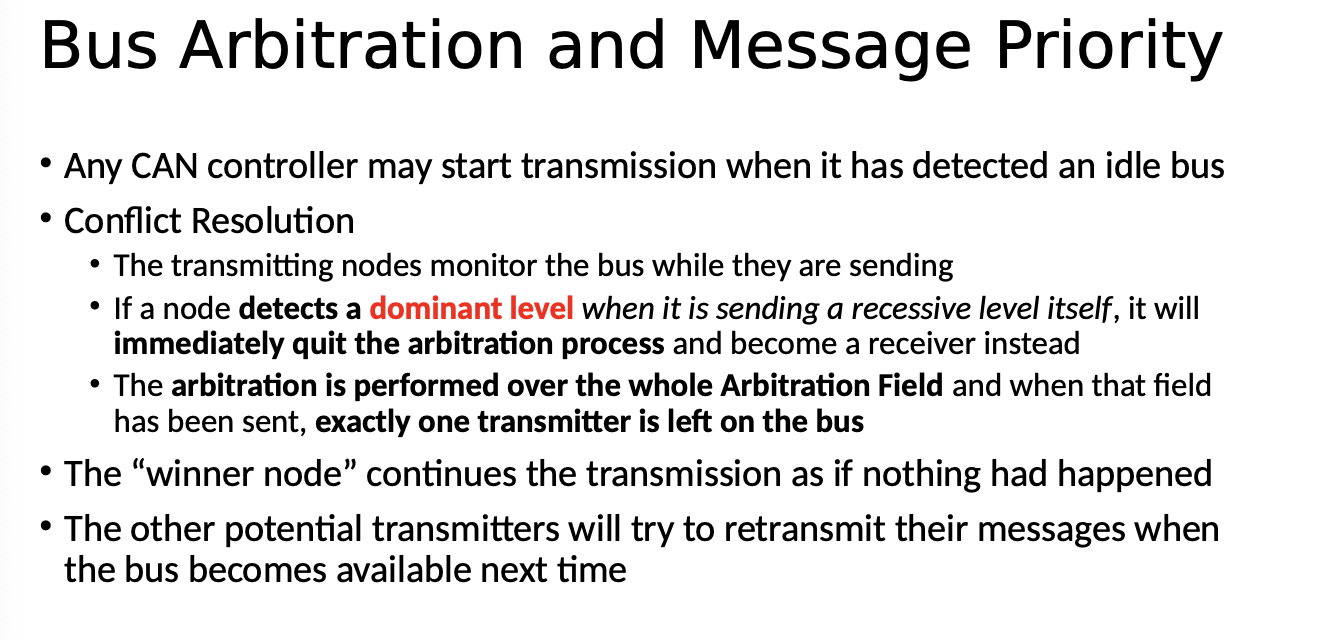
Voltage Difference H:5 L:0 Bit Value 0: - Dominant
Recessive, no difference between high and low -Bit Value 1: Recessive
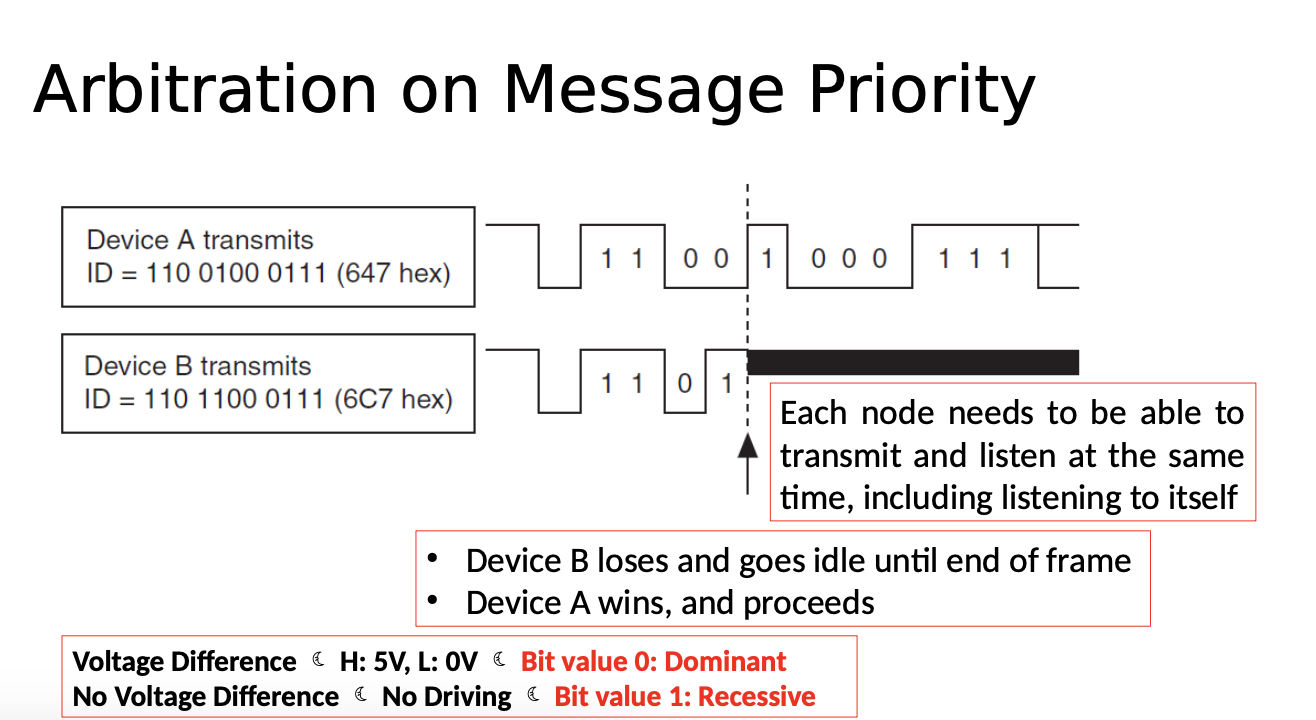
11 bit message id - winner will continue
Key take aways
Bitwise arbitration through differential signals
Review
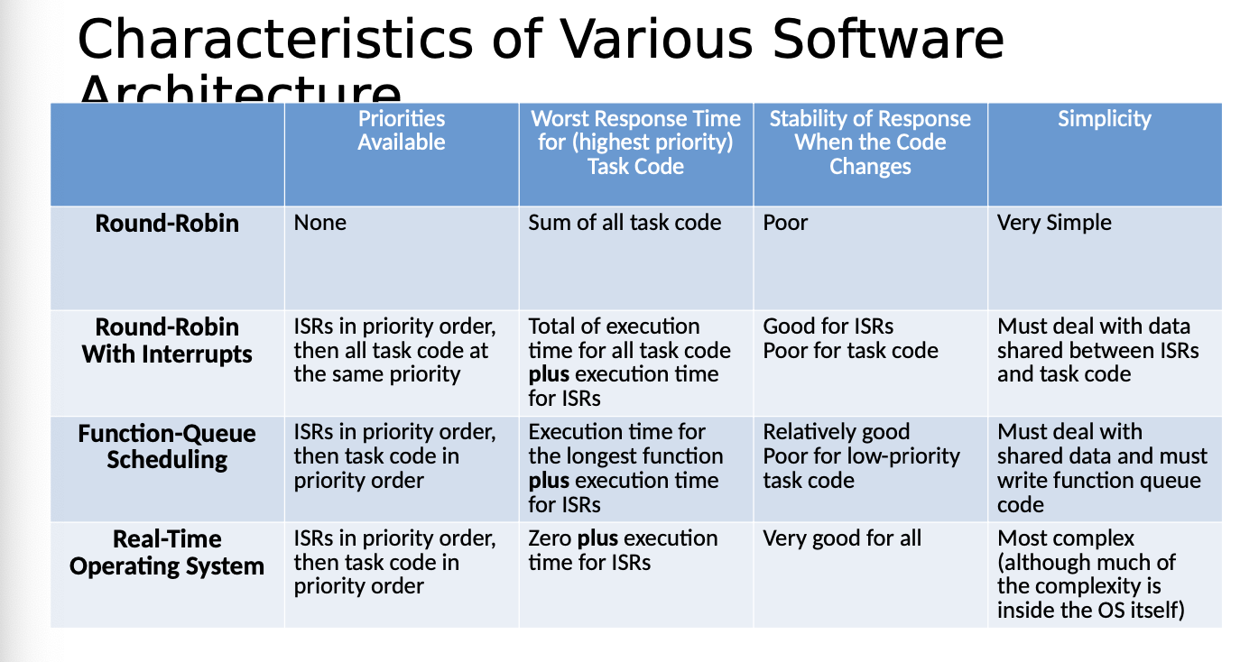
RTOS SCHEDULING
Round - Robin - Big fucking while loop
When can you apply it? What are the problems with it?
Max Time:
Round Robin - With Interrupts Big fucking while loop with interrupts
ISR Generated with io devices and sets flags
Max Time:
No priority with task code
Function Queue Scheduling Architecture
ISR Deal with urgent needs, then adds function pointers to a queue of function pointers...main routine reads pointers and calls functions/tasks
Max Time:
Priority given by queue
RTOS:
Programmer can assign priority to different tasks and that differentiates the priority
Uses a scheduler
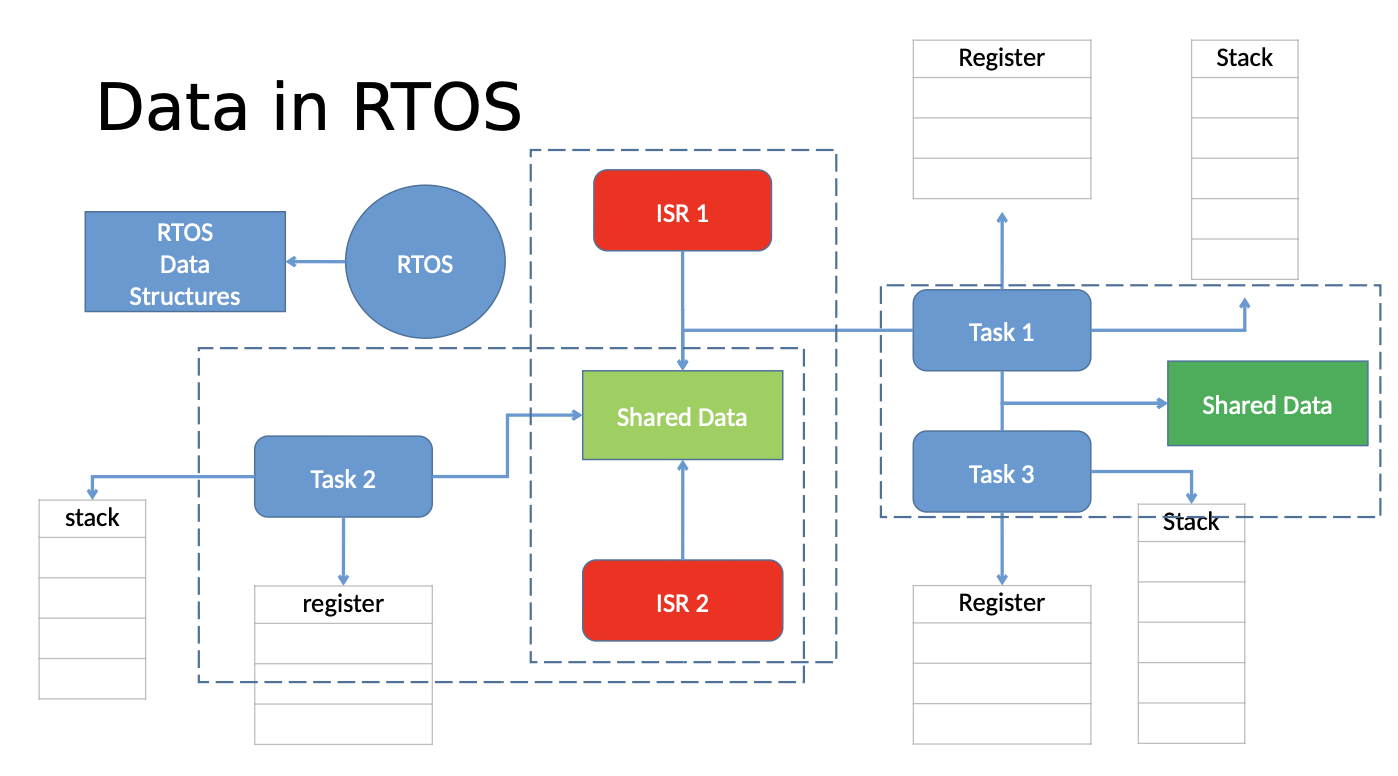
Event is a signal
Communication - data
Reentrant functions
- can be used by more than one task
- will always work correctly, even if RTOS switches from one task to another in the middle of executing the function
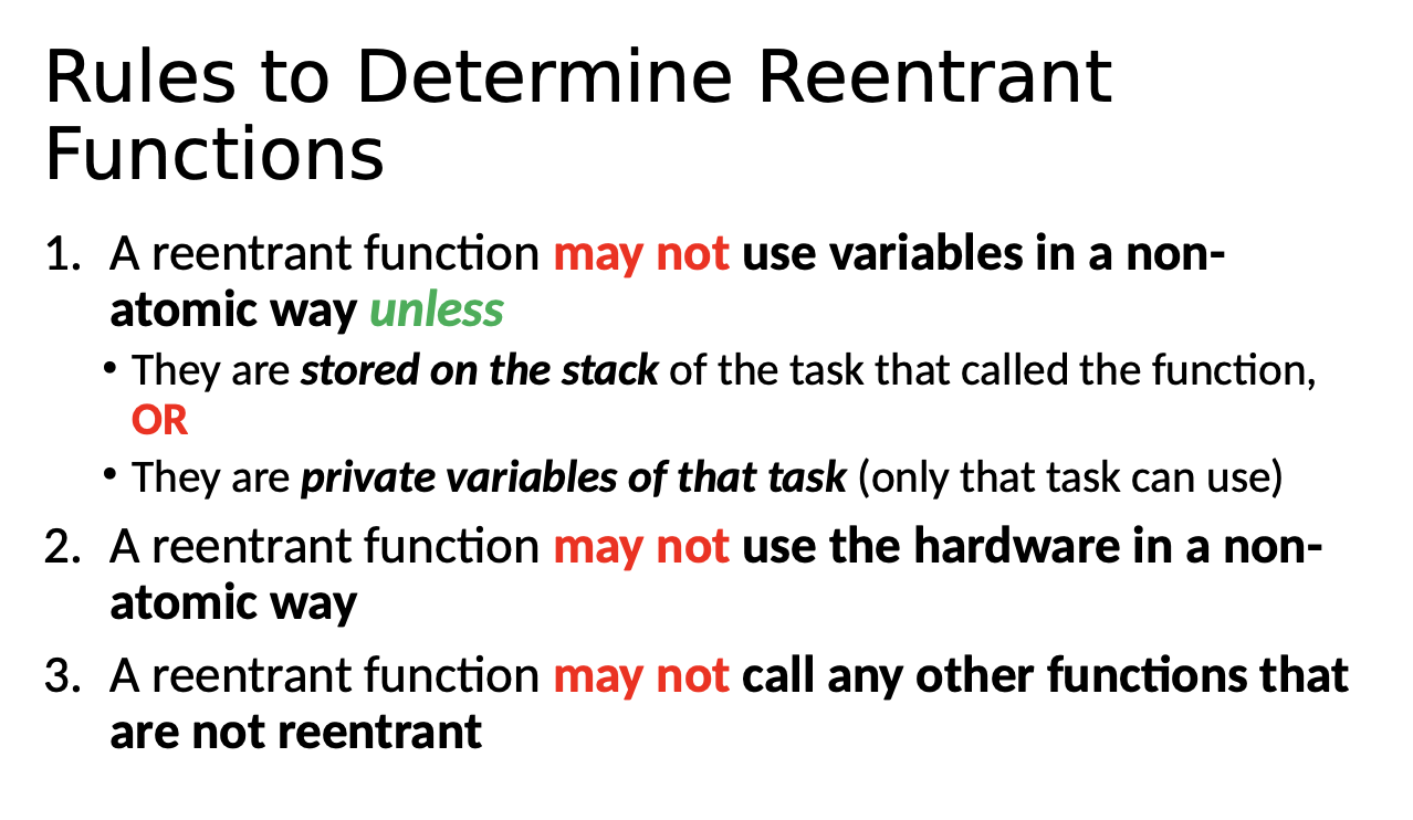
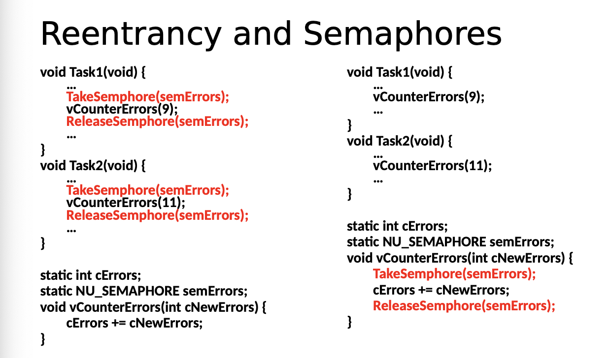
int sumTHISSTATMENTISREENTRANT(int a, int b){
 a = a + b;
 return a;
}
Priority inversion
Bounded - Unbounded
Bounded is two tasks - unbounded is 3 or more
A low level task can prevent a higher priority task from running
When would a scheduler be called in RTOS
When you release a semaphore, mutex, when you finish a task,
When some task/interrupt/etc signals something is ready Post message to queue/mailbox
Priority Ceiling
Very strict - not as flexible as Priority inheritance protocol
Prevent deadlocks - shorten wait time for high priority tasks
Wait time for low priority task.pretty low
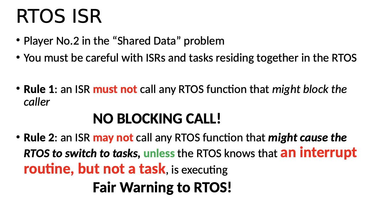
1: Don't take any semaphore
Message Queues/Mailboxes

Memory
Code will be divided into different segments
Major Design Concerns - may use bit mapped management
Space - need memory management system which takes up space...RTOS may disable MMU support and dynamic memory allocation
Canbus
Bitwise arbitration
Differential signals
CSMA